Electronic railway contact net stand column passing device

A technology of electrified railway and catenary, applied in the direction of roads, track superstructure, bridge parts, etc., to achieve the effect of normal power supply

Inactive Publication Date: 2017-10-13
李诚
View PDF0 Cites 1 Cited by
  • Summary
  • Abstract
  • Description
  • Claims
  • Application Information

AI Technical Summary

Problems solved by technology

[0003] The technical problem to be solved by the present invention is to provide a device for crossing the column of the electrified railway catenary, which solves the problem that the main girder of the mechanical arm must be retracted and extended to work when it encounters the column

Method used


Image

  • Electronic railway contact net stand column passing device
  • Electronic railway contact net stand column passing device
  • Electronic railway contact net stand column passing device

Examples


Embodiment Construction

[0016] The following will clearly and completely describe the technical solutions in the embodiments of the present invention with reference to the accompanying drawings in the embodiments of the present invention. Obviously, the described embodiments are only some, not all, embodiments of the present invention. Based on the embodiments of the present invention, all other embodiments obtained by persons of ordinary skill in the art without making creative efforts belong to the protection scope of the present invention.

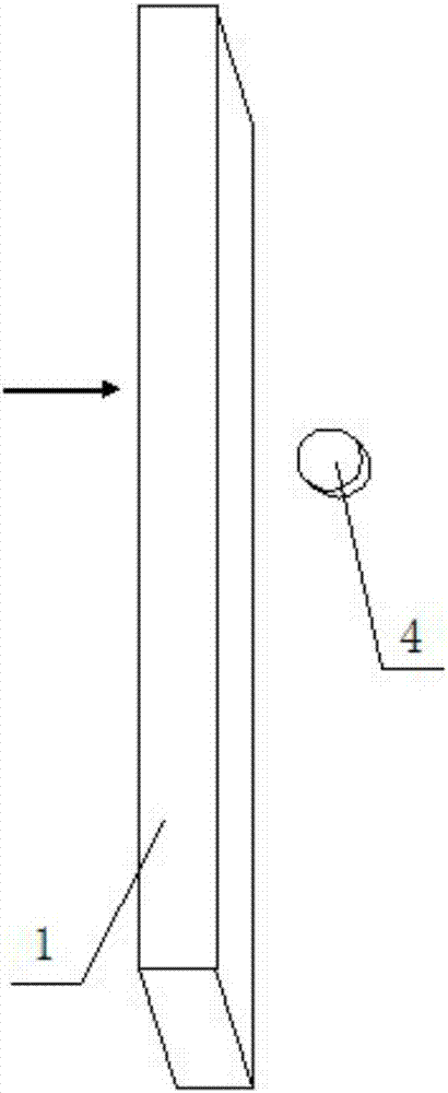
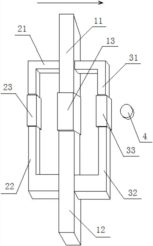
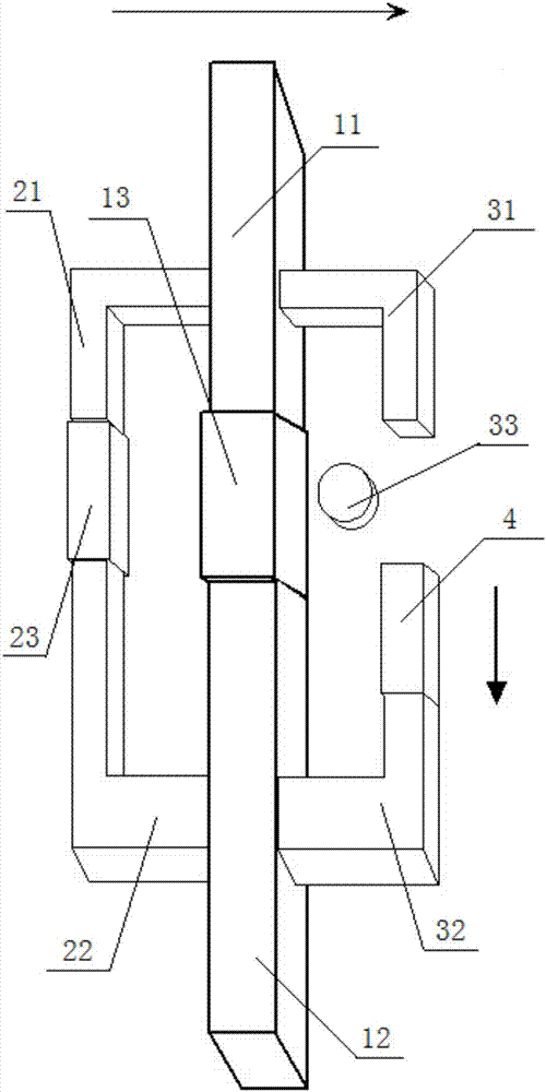
[0017] See figure 2 , the electrified railway catenary column crossing device, including a main beam, a left beam and a right beam connected to both sides of the main beam, the main beam includes an upper main beam 11, a lower main beam 12 and a telescopic sleeve 13 connecting the main beam , the bottom of the upper main beam 11 is set opposite to the top of the lower main beam 12, and the top of the lower main beam 12 is sleeved and connected with a connecti...


PUM


Abstract

The invention discloses an electrified railway catenary column crossing device, which comprises a main beam, a left beam and a right beam connected to both sides of the main beam, and the main beam is divided into an upper main beam, a lower main beam and a telescopic connecting main beam sleeve, and the bottom end of the upper main beam or the top of the lower main beam is sleeved and connected with a main beam telescopic sleeve; the left side beam includes a left upper side beam, a left lower side beam and a left telescopic sleeve, and the left upper side beam The bottom end or the top of the left lower side beam is fitted with a left telescopic sleeve, the right side beam includes a right upper side beam, a right lower side beam and a right telescopic sleeve, and the bottom end of the right upper side beam or the top of the right lower side beam The upper sleeve is connected with a right telescopic sleeve. The present invention utilizes the expansion and contraction effect of the telescopic sleeve, and when the telescopic sleeve is retracted, a gap is formed to realize the avoidance of the column, and the main beam, the left beam and the right beam form gaps in sequence to realize the avoidance, and when any beam body forms When avoiding the gap, the other two beams are in a connected load-bearing state, which does not affect the safety of the overall mechanical equipment.

Description

technical field [0001] The invention relates to the field of electrified railways, in particular to an electrified railway catenary column crossing device. Background technique [0002] The catenary column of the electrified railway plays an important role in supporting the power network, and a column is erected every tens of meters on both sides of the electrified railway. However, the column has a very large impact on the operation of some mechanical construction and testing equipment, resulting in the inability of the mechanical equipment to work continuously. When a construction machine encounters a column, it must take back the equipment extending outside the line, avoiding the column and then stretching out to work, which greatly affects the work efficiency. See figure 1 , a schematic diagram of the relationship between the column and the main beam of the mechanical arm; when the main beam 1 moves to the right, it cannot pass due to the blocking of the column 4. Co...

Claims


Application Information

Patent Timeline
Patent Type & Authority Applications(China)
IPC IPC(8): E01B37/00E01D19/10
CPCE01B37/00E01B2203/00E01D19/106
Inventor 李诚王卸松李建华
Owner 李诚
Why Eureka
Try Eureka