
A shared charging treasure rental machine

A charging treasure and cabinet technology, which can be used in buying and selling/lease transactions, current collectors, electric vehicles, etc., can solve problems such as inability to charge in time, insufficient power of electronic equipment, etc., and achieve the effect of saving manpower

Active Publication Date: 2018-08-31
厦门咻电科技有限公司
View PDF1 Cites 0 Cited by
  • Summary
  • Abstract
  • Description
  • Claims
  • Application Information

AI Technical Summary

Problems solved by technology

[0004] The purpose of the present invention is to provide a shared charging treasure rental machine, which solves the problem that the electronic equipment carried by people on the way out has insufficient power and cannot be charged in time

Method used


Image

  • A shared charging treasure rental machine
  • A shared charging treasure rental machine
  • A shared charging treasure rental machine

Examples


Embodiment 1

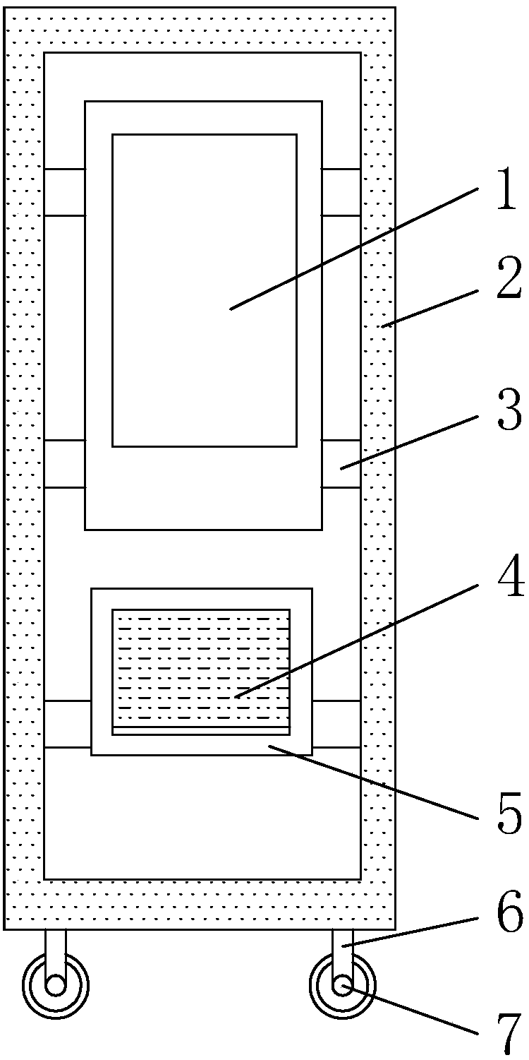
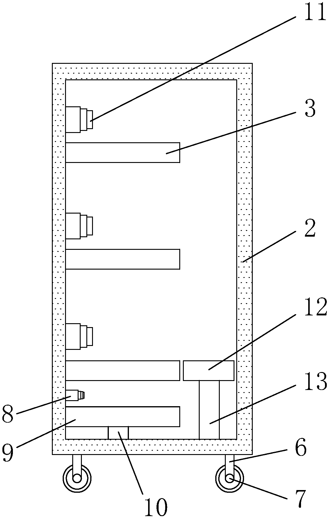
[0036] see Figure 1-3, a shared charging treasure rental machine, comprising a cabinet main body 2, a pulley 7 is connected to the bottom of the cabinet main body 2, the pulley 7 is fixed to the cabinet main body 2 through a foot 6, and a liquid crystal display operation panel 1 is arranged above the front wall of the cabinet main body 2, An outlet 5 is provided below the liquid crystal display operation panel 1, a baffle 4 is fixed on the inside of the outlet 5, a supporting plate 3 is fixed above the inner wall of the cabinet main body 2, and a push telescopic rod 11 is arranged above one end of the supporting plate 3, and the cabinet One side below the inner wall of the main body 2 is fixed with a support rod 10, and the top of the support rod 10 is fixed with a recovery plate 9, and the upper side of the recovery plate 9 is provided with a recovery telescopic rod 8, and the other side below the inner wall of the cabinet main body 2 A lifting platform 13 is fixed on the si...

Embodiment 2

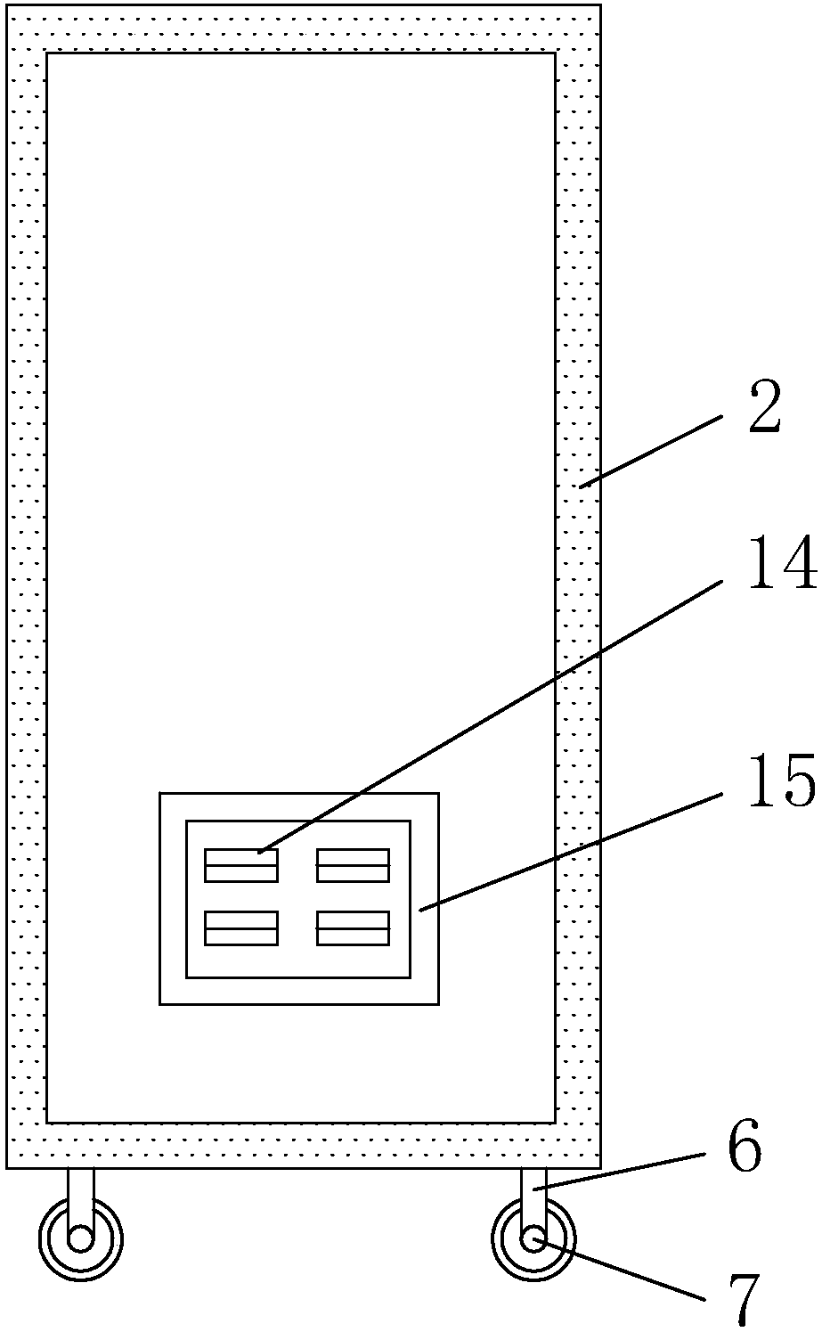
[0039] combine Figure 4 to Figure 8 As shown, this embodiment makes the following improvements on the basis of embodiment 1: a password input device 19 is installed on the front wall of the cabinet body immediately below the liquid crystal display operation screen.

[0040] The password input device includes a first housing 91, a second housing 92 and a cover plate 93 connected in sequence; a finger insertion port 912 through the front and back is formed on the first housing, An installation cavity 914 is formed on the left side of the finger insertion opening, and a first installation opening 913 is formed on the front side of the first housing corresponding to the installation cavity, and a connecting wall 911 is formed on the outer periphery of the first housing. The connecting wall is fixedly connected with the inner wall of the cabinet shell.

[0041] The second housing is a tubular structure that runs through front and back, and a mounting plate 921 is formed on the fr...


PUM


Abstract

The invention discloses a shared-power-bank rental machine which comprises a charging-pile shell and a heat dissipation sheet. A charging-pile fixing base is arranged at the bottom of the charging-pile shell, a display screen is arranged at one end of the front surface of the charging-pile shell, a shading panel is arranged on the front surface of the charging-pile shell and close to the position above the display screen, a charging-cable suspension bracket is arranged at the upper end of one side of the charging-pile shell, a charging-gun fixing seat is arranged on one side of the charging-pile shell and close to the position under the charging-cable suspension bracket, and a fixing-seat thread pillar is arranged on the charging-gun fixing seat and close to one end of the charging-pile shell. Through the charging-gun fixing seat arranged on one side of the charging pile and an annular magnetic closure ring arranged in a fixing-seat annular groove and a charging gun in design, the charging gun is effectively and conveniently fixed on a fixing seat by the aid of the principle of magnetic heteropolar absorption when a user stops using and putting the charging gun to be close to the fixing seat.

Description

technical field [0001] The invention relates to the technical field of shared power bank rental cabinet equipment, in particular to a shared power bank rental machine. Background technique [0002] Shared power bank refers to the charging rental equipment provided by the company. Users only need to scan the QR code on the screen of the device and borrow a power bank "without deposit" with a Zhima credit score of 600 or more. If the credit score is less than 600, they can also pay 100 After the power bank is successfully returned, the deposit can be withdrawn at any time and returned to the account. The rented power bank can be used for free for 1 hour, after 1 hour, 1 yuan per hour, and 10 yuan is capped on the same day, and the required data cable can also be purchased according to the model. [0003] However, when people return the charging treasure, the staff needs to open the charging rental equipment, replace the exhausted charging treasure, put the fully charged charg...

Claims


Application Information

Patent Timeline
Patent Type & Authority Patents(China)
IPC IPC(8): G07F17/00G06Q30/06H02J7/00
CPCG06Q30/0645G07F17/0042H02J7/0013
Inventor 江佳辉
Owner 厦门咻电科技有限公司
Features
  • Generate Ideas
  • Intellectual Property
  • Life Sciences
  • Materials
  • Tech Scout
  • Unparalleled Data Quality
  • Higher Quality Content
  • 60% Fewer Hallucinations
Learn More