A power converter control circuit capable of realizing controller parameter self-tuning

A power converter, parameter self-tuning technology, applied in output power conversion devices, electrical components, etc., can solve problems such as complex algorithms, poor output power quality, and poor adaptability

Active Publication Date: 2019-07-16
HARBIN ENG UNIV
View PDF1 Cites 0 Cited by
  • Summary
  • Abstract
  • Description
  • Claims
  • Application Information

AI Technical Summary

Problems solved by technology

However, the PI controller with fixed parameters has poor adaptability under different working conditions, and it is difficult to ensure that the expected control requirements are met during the dynamic adjustment process such as overshoot and oscillation, especially when the load changes, such problems are more prominent , resulting in poor output power quality
Although the existing PI parameter self-tuning control technology can effectively improve the control effect of the PI controller, there is a problem of complex algorithm, which needs to be further solved

Method used


Image

  • A power converter control circuit capable of realizing controller parameter self-tuning
  • A power converter control circuit capable of realizing controller parameter self-tuning
  • A power converter control circuit capable of realizing controller parameter self-tuning

Examples


Embodiment 1

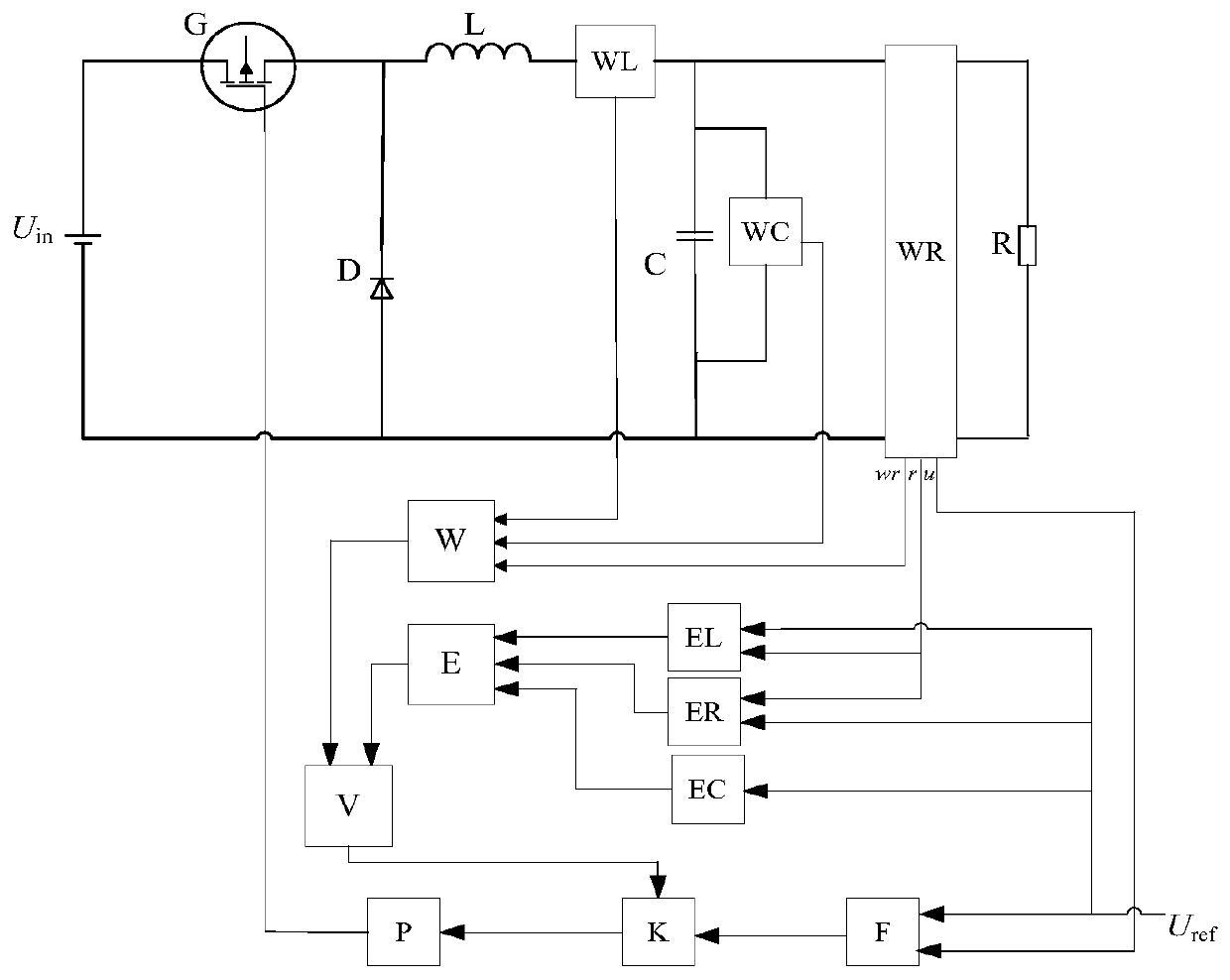
[0102] The power electronic device G, freewheeling diode D, filter inductor L, and filter capacitor C constitute the main circuit of the BUCK type DC-DC converter. The selection and parameter calculation of these devices are similar to the device selection and calculation of the existing BUCK type circuit. The parameter calculations are exactly the same. If it is a power converter of other forms, its main circuit component selection and parameter calculation are also completely consistent with the existing main circuit component selection and parameter calculation methods of this type of power converter.

[0103]The actual energy detection circuit WL of the inductor can be realized by using an existing circuit capable of real-time detection of energy and real-time data communication. For example, a single-chip microcomputer can be used to sample the inductor current through a Hall-type current sensor, and the The corresponding calculation of the current value can calculate the...

Embodiment 2

[0116] The actual energy detection circuit WL of the inductor can be realized by using an existing analog circuit capable of real-time detection of current and multiplication function. For example, the Hall-type current sensor can be used to sample the inductor current, and the multiplication circuit can be used to calculate the energy stored in the inductor, and the analog signal output by the multiplication circuit can be transmitted to other circuits. The design of the multiplication circuit is the same as that of the existing The design method of the multiplication circuit is the same.

[0117] The actual energy detection circuit WC of the capacitor can be realized by using an existing analog circuit capable of real-time detection of voltage and multiplication function. For example, a Hall-type voltage sensor can be used to sample the capacitor voltage, and a multiplication circuit can be used to calculate the energy stored in the capacitor, and the analog signal output by...


PUM


Abstract

The invention provides a power converter control circuit capable of realizing controller parameter self-tuning. Including the main circuit of the power converter, it also includes the inductance actual energy detection circuit WL, the capacitance actual energy detection circuit WC, the output detection circuit WR, the actual energy analysis circuit W, the inductance expected energy calculation circuit EL, the capacitance expected energy calculation circuit EC, the output Expected energy calculation circuit ER, expected energy analysis circuit E, energy analysis circuit V, adjustable PI controller circuit K, drive signal generation circuit P, difference calculation circuit F. The present invention proposes a control circuit for adjusting the PI parameters of the controller based on the energy stored in the inductor and capacitor in the power converter and the difference between the actual output energy of the power converter and the corresponding expected energy. On the premise of effectively controlling the power converter, the defects of the existing PI controller can be solved.

Description

technical field [0001] The invention relates to a control circuit of a power converter. Background technique [0002] In the controller design of the power converter, the PI controller is widely used because of its advantages of high reliability, good robustness, simple and effective algorithm, etc. However, the PI controller with fixed parameters has poor adaptability under different working conditions, and it is difficult to ensure that the expected control requirements are met during the dynamic adjustment process such as overshoot and oscillation, especially when the load changes, such problems are more prominent , resulting in poor output power quality. Although the existing PI parameter self-tuning control technology can effectively improve the control effect of the PI controller, there is a problem of complex algorithm, which needs to be further solved. Contents of the invention [0003] The object of the present invention is to provide a power converter control c...

Claims


Application Information

Patent Timeline
Patent Type & Authority Patents(China)
IPC IPC(8): H02M1/00
CPCH02M1/00H02M1/0003
Inventor 张强白峻汀王云鹏宿小明付兴利张炜王言畅孙维义任彦光桑杰汪寅乔
Owner HARBIN ENG UNIV
Why Eureka
Try Eureka