Superheater for industrial incineration boiler

A boiler and superheating technology, used in lighting and heating equipment, incinerators, steam superheating, etc., can solve the problems of easy tube bursting, short operation cycle of superheater, repeated tube bursting, etc., to prolong the operation cycle and avoid smoke. The effect of reducing the gas corridor and reducing the problem of burst pipes

Active Publication Date: 2017-10-17
烟台国新环保科技有限公司
View PDF6 Cites 0 Cited by
  • Summary
  • Abstract
  • Description
  • Claims
  • Application Information

AI Technical Summary

Problems solved by technology

[0002] In the incineration boiler, due to the very harsh environment of the workpiece of the superheater, the heat exchange tube of the superheater of the incineration boiler is often prone to the problem of tube explosion during operation (usually after about 15 months of operation). Even shorter run times due to pipeline quality or other reasons
[0003] At present, for the problem of the superheater burst tube of the incineration boiler, it is usually repaired by immediately shutting down the furnace to cool down, and repairing by welding and replacing a section of pipe; the problem with this treatment method is: after a period of operation, the burst tube will be repaired Repeated occurrence on the same cross-section of the same canal and agreed area

Method used


Image

  • Superheater for industrial incineration boiler
  • Superheater for industrial incineration boiler
  • Superheater for industrial incineration boiler

Examples


Embodiment 1

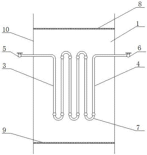
[0017] Such as figure 1 As shown, a superheating equipment for industrial incineration boilers includes several heat exchange tubes arranged in the furnace chamber 1, the heat exchange tubes include a first heat exchange tube 3 and a second heat exchange tube 4, the heat exchange tubes The heat pipes are all vertically arranged in the furnace chamber 1 with equal intervals between them. The furnace chamber 1 also includes an inlet header 5, an outlet header 6 and a U-shaped overheating pipe 7. The inlet header The box 5 is used to connect the first heat exchange tube 3 and the U-shaped overheating tube 7, and the outlet header 6 is used to connect the second heat exchange tube 4 and the U-shaped overheating tube 7. The furnace cavity 1 also includes a first metal filter plate 8 and a second metal filter plate 9, the first metal filter plate 8 and the second metal filter plate 9 are arranged horizontally, and both ends are connected to the furnace wall 10, so The first metal f...

Embodiment 2

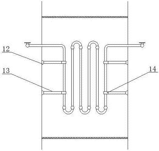
[0023] Example two as figure 2 As shown, the furnace cavity 1 also includes a lateral positioning device 12, the lateral positioning device 12 includes a first connecting rod 13 arranged on the furnace wall 10, and the first connecting rod 13 is used to connect the first Pipe clamp 14, the first pipe clamp 14 is used to clamp the heat exchange tube.

[0024] Specifically, in order to keep the transverse pitch of the overheated tubes and the flatness of the tube bundle plane, a first tube clamp 14 is installed on the overheated tube, and the first tube clamp 14 is connected with all the horizontal positioning devices 12 The first connecting rod 13 is connected, and the upper and lower parts of the overheating pipe are clamped by the first pipe clamp 14. In order to ensure that the first pipe clamp 14 has sufficient strength at high temperature, the material is Cr18Ni9Ti.

Embodiment 3

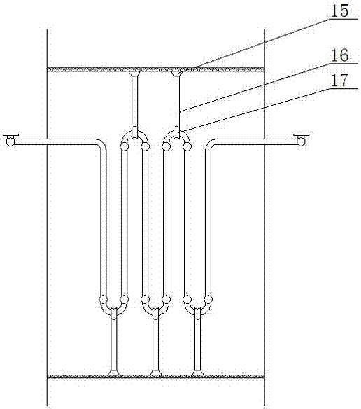
[0026] Such as image 3 As shown, the furnace cavity 1 also includes a longitudinal positioning device 15, and the longitudinal positioning device 15 includes a second connecting rod 16 arranged on the first metal filter plate 8 and the second metal filter plate 9, so The second connecting rod 16 is used for connecting the second pipe clamp 17, and the second pipe clamp 17 is used for clamping the U-shaped overheating pipe 7.

[0027] Specifically, in addition to adding a horizontal positioning device 12 to limit the lateral displacement of the superheated tube, it is also necessary to add a longitudinal positioning device 15, which can reduce the radiation of the superheated tube by high-temperature flue gas, and the vertical positioning device 15 and the first A metal filter plate 8 and the second metal filter plate 9 are welded to have good heat conduction effect and relatively fixed.


PUM


Abstract

The invention discloses a superheater for an industrial incineration boiler. The superheater comprises a plurality of heat exchanging pipes arranged in a boiler chamber, the heat exchanging pipes comprise the first heat exchanging pipes and the second heat exchanging pipes, the heat exchanging pipes are all vertically arranged in the boiler chamber, and the distances between every two heat exchanging pipes are equal; the boiler chamber further comprises inlet headers, outlet headers and U-shaped superheater tubes internally, the inlet headers are used for connecting the first heat exchanging pipes and the U-shaped superheater tubes, and the outlet headers are used for connecting the second heat exchanging pipes and the U-shaped superheater tubes; and the boiler chamber further comprises a first metal filtering plate and a second metal filtering plate, the first metal filtering plate and the second metal filtering plate are arranged horizontally, the two ends of the first metal filtering plate and the second metal filtering plate are connected with the wall of the boiler, the first metal filtering plate is located above the heat exchanging pipes, and the second metal filtering plate is located below the heat exchanging pipes.

Description

technical field [0001] The invention relates to the field of incineration boilers, in particular to a superheating device for industrial incineration boilers. Background technique [0002] In the incineration boiler, due to the very harsh environment of the workpiece of the superheater, the heat exchange tube of the superheater of the incineration boiler is often prone to tube bursting during operation (usually the tube bursts after about 15 months of operation), due to overheating The operating cycle is even shorter due to the pipe quality of the device or other reasons. [0003] At present, for the problem of the superheater burst tube of the incineration boiler, it is usually repaired by immediately shutting down the furnace to cool down, and repairing by welding and replacing a section of pipe; the problem with this treatment method is: after a period of operation, the burst tube will be repaired It occurs repeatedly on the same cross-section of the same tube and agreed...

Claims


Application Information

Patent Timeline
Patent Type & Authority Applications(China)
IPC IPC(8): F23G5/44F22G3/00
CPCF22G3/008F23G5/44
Inventor 张晨成
Owner 烟台国新环保科技有限公司
Why Eureka
Try Eureka