Continuous mud pressure monitoring communication device for ocean engineering platform

A technology of mud pressure and marine engineering, which is applied in the direction of earth movers/shovels, mechanically driven excavators/dredgers, construction, etc. It can solve the problems of not timely adjusting the pressure of large and small mud, easy to break through pipelines, etc., to achieve convenience Control, reduce cumbersomeness, and increase the effect of export discharge

Inactive Publication Date: 2021-11-16
重庆鑫杰力科技有限公司
View PDF1 Cites 0 Cited by
  • Summary
  • Abstract
  • Description
  • Claims
  • Application Information

AI Technical Summary

Problems solved by technology

[0003] The purpose of the present invention is to at least solve one of the technical problems in the prior art, and provide a continuous mud pressure monitoring communication device for offshore engineering platforms, which can solve the problem that the staff does not adjust the pressure in time and the mud is easy to break through the pipeline

Method used


Image

  • Continuous mud pressure monitoring communication device for ocean engineering platform
  • Continuous mud pressure monitoring communication device for ocean engineering platform
  • Continuous mud pressure monitoring communication device for ocean engineering platform

Examples


Embodiment 1

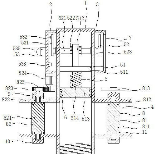
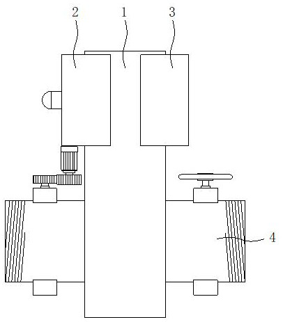
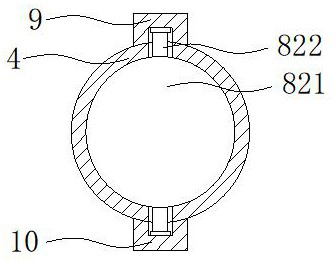
[0032] see Figure 1-6 , the present invention provides a technical solution: a continuous mud pressure monitoring communication device for offshore engineering platforms, including a hollow cylinder 1, a detection and alarm mechanism 5 and an adjustment mechanism 8, and a first protective shell 2 is fixedly installed on one side of the hollow cylinder 1 , the other side of the hollow cylinder 1 is fixedly installed with a second protective shell 3, both sides of the hollow cylinder 1 are fixedly installed with two sets of mud discharge cylinders 4, both sides of the hollow cylinder 1 are provided with water outlets, and the two sets of water outlets They are respectively located on one side of the two groups of mud discharge cylinders 4. The detection and alarm mechanism 5 includes a transmission assembly 51, a pressure value assembly 52 and an alarm assembly 53. The transmission assembly 51 is located inside the hollow cylinder 1, and the pressure value assembly 52 is located...

Embodiment 2

[0035] see Figure 1-6 On the basis of Embodiment 1, the transmission assembly 51 includes a fixed plate 511, a movable rod 512, a piston 513 and a spring 514, the outer wall of the fixed plate 511 is fixedly installed on the inner wall of the hollow cylinder 1, and the outer wall of the movable rod 512 is slidably installed on the fixed On the plate 511, the top of the piston 513 is fixedly installed on the bottom of the movable rod 512, the spring 514 is sleeved on the outer wall of the movable rod 512, the top of the spring 514 is fixedly installed on the bottom of the fixed plate 511, and the bottom of the spring 514 is connected to the piston 513. The top of the piston 513 is fixedly installed, and the outer wall of the piston 513 is provided with a first sealing groove, and the first sealing ring 6 is fixedly installed in the first sealing groove, and the outer walls of the first sealing ring 6 and the piston 513 are in contact with the inner wall of the hollow cylinder 1...


PUM


Abstract

The invention discloses a continuous mud pressure monitoring communication device for an ocean engineering platform, and relates to the technical field of ocean engineering. The continuous mud pressure monitoring communication device for the ocean engineering platform comprises a hollow cylinder, a detection alarm mechanism and an adjusting mechanism. One side of the hollow cylinder is fixedly provided with a first protective shell, the other side of the hollow cylinder is fixedly provided with a second protective shell, and the two sides of the hollow cylinder are each fixedly provided with two sets of mud discharging cylinders. Through threads in the hollow cylinder, the hollow cylinder can be installed at an outlet of a slurry pipeline in a threaded mode, so that the interior of the hollow cylinder is communicated with the interior of the slurry pipeline, the pressure intensity in the hollow cylinder is the same as that in the slurry pipeline, then through cooperative use of a fixing plate, a movable rod, a piston, a spring, a rotating shaft, a transmission gear and a pressure pointer, the pressure intensity in the slurry pipeline can be detected, and the detected pressure intensity value can be displayed through the scales on a glass sheet, so that a worker can conveniently and reasonably regulate and control the pressure intensity in the slurry pipeline.

Description

technical field [0001] The invention relates to the technical field of ocean engineering, in particular to a continuous mud pressure monitoring communication device for an ocean engineering platform. Background technique [0002] With the continuous development of society, people pay more and more attention to the development of offshore oil, and in the process of drilling the seabed oil, a large amount of mud will flow into the excavation port, which leads to the need to pass the mud through the pipeline before oil collection For extraction, in order to enable the mud to be extracted smoothly from the seabed, it is necessary to ensure that the pressure in the pipeline is maintained within a certain range during the extraction process. The existing pressure monitoring device can only perform simple measurement of the pressure in the pipeline. The value needs to be observed by the staff with naked eyes, and then the pressure in the pipeline can be manually adjusted by manuall...

Claims


Application Information

Patent Timeline
Patent Type & Authority Applications(China)
IPC IPC(8): E02F3/90
CPCE02F3/907
Inventor 翟波王丹郭元友
Owner 重庆鑫杰力科技有限公司
Why Eureka
Try Eureka