Backlight drive circuit

A technology of backlight drive circuit and comparison circuit, which is applied to instruments, static indicators, etc., and can solve problems such as deformation damage, reflection sheet or light guide plate deformation damage, high operating temperature of liquid crystal display devices, etc.

Inactive Publication Date: 2017-10-17
KUSN INFOVISION OPTOELECTRONICS
View PDF6 Cites 12 Cited by
  • Summary
  • Abstract
  • Description
  • Claims
  • Application Information

AI Technical Summary

Problems solved by technology

[0005] like Figure 2a As shown, the LED light bar 11 is close to the reflector or the light guide plate and other components 20, and the temperature of the LED light bar 11 rises after being lit by the LED driver chip 12, especially when the ambient temperature is high, it may exceed the reflector or the light guide plate. The temperature resistance value of components 20 such as light boards, and then problems such as deformation and damage occur (such as Figure 2b shown)
[0006] However, when adjusting the brightness of the backlight, especially when the ambient temperature is high, the LED light bar 11 will generate heat, which will cause the operating temperature of the liquid crystal display device to be too high, causing problems such as deformation and damage of the reflective sheet or the light guide plate, etc.

Method used


Image

  • Backlight drive circuit
  • Backlight drive circuit
  • Backlight drive circuit

Examples


Embodiment Construction

[0025] Various embodiments of the invention will be described in more detail below with reference to the accompanying drawings. In the various drawings, the same elements are denoted by the same or similar reference numerals. For the sake of clarity, various parts in the drawings have not been drawn to scale.

[0026] The specific implementation manners of the present invention will be further described in detail below in conjunction with the accompanying drawings and embodiments.

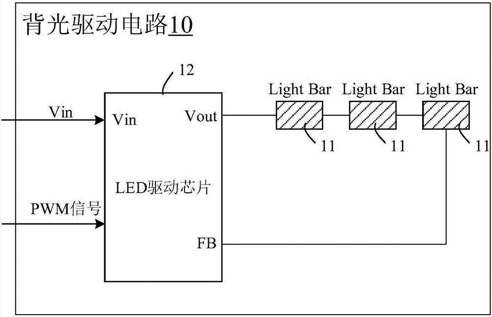
[0027] image 3 A circuit diagram of a backlight driving circuit provided according to an embodiment of the present invention is shown. Such as image 3 As shown, the backlight drive circuit 10 includes an LED light bar 11 , an LED drive chip 12 , a temperature detection circuit 13 , a comparison circuit 14 and a reference current generation circuit 15 .

[0028] Wherein, the LED driving chip 12 is used for outputting backlight current to drive the LED light bar 11 .

[0029] In this embodimen...


PUM


Abstract

A backlight drive circuit comprises an LED light bar, an LED driving chip used for outputting a backlight current to drive the LED light bar; a temperature detection circuit used for detecting the temperature of the LED light bar and outputting a sampling voltage; a comparison circuit used for generating a control signal according to the sampling voltage and a reference voltage; a reference current generating circuit used for adjusting a reference cureent of the LED driving chip according to the control signal, wherein the LED driving chip is also used for adjusting the backlight current of the LED light bar according to the reference current. According to the backlight drive circuit provided by the present invention, by using a thermistor temperature detection circuit arranged on the LED light bar to output the sampling voltage, controlling the reference current of the LED driving chip according to the sampling voltage and the reference voltage, and further regulating and controlling an output current of the LED driving chip according to the current temperature, the LED light bar keeps working with the backlight current matching the current temperature during the temperature change process.

Description

technical field [0001] The present invention relates to the field of display technology, and more particularly, to a backlight driving circuit. Background technique [0002] A liquid crystal display (LCD, Liquid Crystal Display) has many advantages such as a thin body, power saving, and no radiation, and has been widely used. Most of the liquid crystal display devices currently on the market are backlight liquid crystal display devices, which include a liquid crystal panel and a backlight module. The working principle of the liquid crystal panel is to place liquid crystal molecules between two parallel glass substrates. There are many vertical and horizontal small wires between the two glass substrates. The direction of the liquid crystal molecules is controlled by electrifying or not, and the light of the backlight module is refracted. Come out to generate the picture. Since the liquid crystal panel itself does not emit light, the light source provided by the backlight mo...

Claims


Application Information

Patent Timeline
Patent Type & Authority Applications(China)
IPC IPC(8): G09G3/34
CPCG09G3/3406
Inventor 刘胜利
Owner KUSN INFOVISION OPTOELECTRONICS
Why Eureka
Try Eureka