Pipe sleeve puller

A technology of puller and sleeve, which is applied in the field of machinery, can solve the problems of not being widely used, the extension arm is suspended in the air, and the pulling range of the puller is limited, so as to solve the problem of sliding or breaking of the pull claw and wide application Effect

Pending Publication Date: 2017-10-20
汤生辉
View PDF6 Cites 2 Cited by
  • Summary
  • Abstract
  • Description
  • Claims
  • Application Information

AI Technical Summary

Problems solved by technology

However, it is not difficult to find that when the spreader is in the stretched state of the spreader arm, the spreader is too far from the pull hook on the spreader arm, which will easily cause the spreader arm to hang in the air. It is easy to slide off and break the hook at the end of the spreader arm. In addition, the spreader is fixed, which limits the pulling range of the puller and cannot be widely used.

Method used


Image

  • Pipe sleeve puller

Examples


no. 1 example

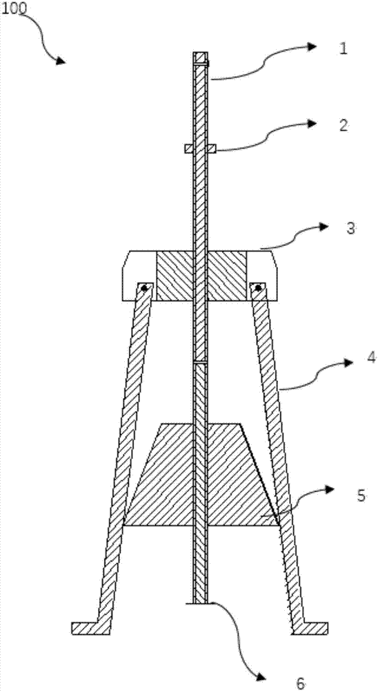
[0018] Such as figure 1 As shown, the longitudinal sectional view of the sleeve puller 100 includes: a screw 1 , a compression nut 2 , a claw seat 3 , a claw 4 , a conical expander 5 and a detachable baffle 6 .

[0019] One end of the screw 1 is a right-handed thread, the other end is a left-handed thread, and the center of the claw seat 3 is provided with a threaded through hole. Both ends of the screw 1 are threaded in different directions. When the screw 1 is turned, the conical expander 5 must be close to the claw seat 3 or away from the claw seat 3; more preferably, it can be connected between the screw 1 and the claw seat 3 The end is provided with a through hole, the center line of the through hole is perpendicular to the axis of the screw rod 1. This through hole is an operation hole, and an iron bar can be inserted in the through hole to facilitate the rotation of the screw rod 1; more preferably, the lower end of the screw rod 1 is installed A detachable baffle 6 is...

no. 2 example

[0025] The difference between the sleeve puller of the second embodiment of the present invention and the first embodiment is that the contact surface between the bent portion of the pull claw 4 and the sleeve is provided with knurling, and the knurling can be straight grain knurling or Knurled knurling; the side wall of the conical expander 5 is provided with guide rail grooves according to the number of pull claws 4, and the pull claws 4 slide and fit with the guide rail grooves.

[0026] When the pipe sleeve that needs to be pulled out is not a through hole, the puller can press the pull claw 4 on the inner wall of the pipe sleeve. The friction force between the claw 4 and the inner wall of the pipe sleeve is increased, and the sliding of the claw 4 is avoided when pulling out. More preferably, the knurling can be straight grain knurling or net knurling; the conical expander 5 is set There are guide rail grooves so that the pull claws are not easy to shake, and the conical ...


PUM


Abstract

The invention relates to a pipe sleeve puller. The pipe sleeve puller is characterized by comprising a screw rod, a pressing nut, a pulling claw seat, a conical expander and at least two pulling claws, wherein left-hand threads are formed on one end of the outer wall of the screw rod, right-hand threads are formed on the other end of the outer wall of the screw rod, the screw rod is in threaded connection with the pulling claw seat through the central axis of the pulling claw seat, the pressing nut is arranged on the connecting end of the screw rod and the pulling claw seat, one end of each pulling claw is hinged to the pulling claw seat, bending parts are arranged on the other ends of the pulling claws, the conical expander is a conical circular truncated cone, the screw rod is in threaded connection with the conical expander through the central axis of the conical expander, and the small-diameter end of the conical expander faces towards the pulling claw seat. The conical expander is arranged, so that the stress point of a claw hook is close to the expanded stress points of the pulling claws when the pulling claws are expanded, the pulling claws are prevented from sliding down or breaking due to long distance, and the expanded amplitude of the pulling claws is increased by a plurality of conical expanders of which the diameters of the lower bottom surfaces are different, so that the puller is widely applied.

Description

technical field [0001] The invention belongs to the field of machinery, and relates to a dismantling tool, in particular to a pipe sleeve puller. Background technique [0002] At present, in the maintenance of various machines, especially in the maintenance process of some sleeve parts with many components, due to the interference between the sleeve and internal or external parts, it is very difficult to disassemble, and destructive disassembly is often carried out in the end, which not only gives Maintenance work is extremely difficult and increases maintenance costs. [0003] In view of the above problems, those skilled in the art have sought some technical improvements, such as the "internal combustion engine cylinder liner puller" provided in the patent CN2510228Y, which is composed of a pressing plate, a screw, and a bolt, and a lifting plate is provided in the middle of the screw. The lifting plate is connected with the spreading arm through the connecting piece, the ...

Claims


Application Information

Patent Timeline
IPC IPC(8): B23P19/04
CPCB23P19/04
Inventor 汤生辉
Owner 汤生辉
Why Eureka
Try Eureka