Special milling clamp for machining breaker base U-shaped waist

A technology of circuit breakers and bases, which is applied in the direction of manufacturing tools, metal processing equipment, metal processing machinery parts, etc., can solve the problems of high production cost, long machine time, low scrap rate, etc., and achieves low manufacturing cost and reduced mobility. Time and productivity improvement effect

Pending Publication Date: 2017-10-20
SUZHOU INST OF INDAL TECH
View PDF6 Cites 0 Cited by
  • Summary
  • Abstract
  • Description
  • Claims
  • Application Information

AI Technical Summary

Problems solved by technology

The process of this method is relatively concentrated, the product quality can be well guaranteed, and the scrap rate is low, but the product structure is relatively simple, the overall accuracy requirements are not high, and re-clamping is required when milling the U-shaped waist, which takes up machine time long, high production cost

Method used


Image

  • Special milling clamp for machining breaker base U-shaped waist
  • Special milling clamp for machining breaker base U-shaped waist
  • Special milling clamp for machining breaker base U-shaped waist

Examples


Embodiment Construction

[0024] The present invention will be described in detail below with reference to the accompanying drawings and in combination with embodiments.

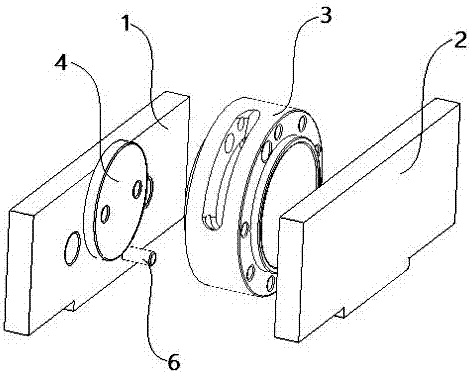
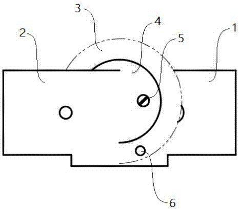
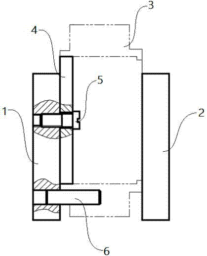
[0025] see Figure 1-3 As shown, a special milling fixture for processing the U-shaped waist of the circuit breaker base is composed of a positioning plate 1 installed on the fixed jaw of the vise and a movable plate 2 installed on the movable jaw of the vise; the positioning plate 1 The middle part of the side is provided with a positioning disc 4 for positioning the circuit breaker base 3, the positioning disc 4 is fixed on the positioning plate 1 by two slotted cylindrical head screws 5, and the positioning disc The upper part of 4 is higher than the upper end surface of the positioning plate 1; the lower part of the inner surface of the positioning plate 1 is provided with a short pin 6 for determining the U-shaped waist milling angle, and the short pin 6 is located on the positioning disc 4, and located on one side of the verti...


PUM


Abstract

The invention discloses a special milling clamp for machining a breaker base U-shaped waist. The special milling clamp is composed of a positioning plate arranged on a flat tongs fixed jaw and a movable plate arranged on a flat tongs movable jaw. A positioning disc is fixed to the middle portion of the inner side face of the positioning plate through two slotted cylinder head screws, and the upper portion of the positioning disc protrudes out of the upper end face of the positioning plate. A short pin is arranged at the lower portion of the inner side face of the positioning plate, located below the positioning disc and located on one side of the perpendicular bisector of the positioning plate. When a workpiece is clamped on the special milling clamp, the positioning disc on the positioning plate is embedded in an inner hole in the rear portion of the workpiece, the short pin is inserted in a ratchet wheel installing hole of the workpiece, and the workpiece is tightly pressed on the positioning plate through the movable plate. According to the special milling clamp, positioning is conducted through the short pin and the positioning disc, the milling angle of the U-shaped waist is determined, tight clamping is conducted through the movable plate arranged on the flat tongs movable jaw, component precision is controlled through the positioning precision of the clamp, the machining quality is guaranteed, clamping is convenient, and the production efficiency is greatly improved.

Description

technical field [0001] The invention belongs to the field of circuit breaker base processing fixtures, in particular to a special milling fixture for processing the U-shaped waist of the circuit breaker base. Background technique [0002] The base of a standard high-voltage AC SF6 circuit breaker will have a U-shaped waist with a width of 17.2mm and an included angle of 87.6° milled out on its side, but for now, this is still a difficult point in the processing of the circuit breaker base. [0003] When using ordinary machine tools for manual processing, the U-shaped waist with a width of 17.2mm and an included angle of 87.6° is processed by the marking-milling-turning clamping-milling method. The processing time of this method is too long, and the U-shaped waist The angle cannot be guaranteed, and its position with the Φ11mm holes on the left and right sides cannot be accurately controlled, so the product quality cannot be reliably guaranteed, resulting in high scrap rate a...

Claims


Application Information

Patent Timeline
Patent Type & Authority Applications(China)
IPC IPC(8): B23Q3/06
CPCB23Q3/066
Inventor 屠春娟周捷张朦
Owner SUZHOU INST OF INDAL TECH
Why Eureka
Try Eureka