A single-ended traveling wave fault location method for transmission lines

A technology for fault distance measurement and transmission lines, which is applied to radio wave measurement systems, fault locations, and measurement devices, can solve problems such as the difficulty of determining the nature of the second traveling wave wave head, and achieve improved reliability and effectiveness and distinctive features Effect

Inactive Publication Date: 2011-12-21
SHANDONG UNIV
View PDF5 Cites 43 Cited by
  • Summary
  • Abstract
  • Description
  • Claims
  • Application Information

AI Technical Summary

Problems solved by technology

It effectively solves the problem that the nature of the second traveling wave head is not easy to judge in the conventional single-ended ranging algorithm by using the initial traveling wave in the reverse polarity direction, and realizes single-ended fault ranging based on the judged result

Method used


Image

  • A single-ended traveling wave fault location method for transmission lines
  • A single-ended traveling wave fault location method for transmission lines
  • A single-ended traveling wave fault location method for transmission lines

Examples


Embodiment Construction

[0029] The present invention will be further described below in conjunction with the accompanying drawings and embodiments.

[0030] Working principle of the present invention is:

[0031] 1.1 Waveform recognition methods of different bus types

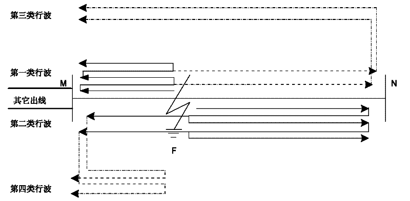
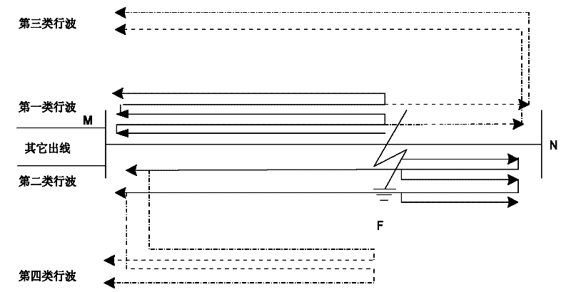
[0032] In the process of traveling wave fault location, the refraction and reflection characteristics of current traveling waves have a great relationship with the types of busbars at both ends of the fault line. From the perspective of considering traveling wave refraction, the busbar types of transmission lines can be divided into the following three categories:

[0033] (1) There is only one outgoing line with a step-up or step-down transformer

[0034] (2) There are two outgoing lines in the busbar, whether there is a transformer or not

[0035] (3) In addition to the faulty line, there are at least two other outgoing lines on the busbar, whether there is a transformer or not

[0036] The current traveling wave will undergo ca...


PUM


Abstract

The invention relates to a single-end fault ranging method based on initial reversed-polarity directional traveling wave detection, which can effectively realize single-end traveling wave fault ranging and has high reliability and high accuracy. The method comprises the following steps: (1) when a traveling wave fault ranging device is started, testing the arriving time t1 of the line modular component of the initial traveling wave of a fault, and extracting traveling wave signals in the time interval [0, 2L/v], wherein L indicates the length of the line, and v indicates the wave speed of theline module component; (2) testing the initial reversed-polarity directional traveling wave in the time interval, calculating the difference of the arriving time of the line modular component of the initial reversed-polarity directional traveling wave and the arriving time of the line modular component of the initial traveling wave of the fault, determining whether the fault is a nearby fault or a remote fault with reference to Curve Chart 3, and accordingly determining the section with the fault point; (3) judging the properties of the second arriving wave head through the determined fault section; and (4) determining final ranging results through the initial traveling wave and the wave head of the second traveling wave of the fault.

Description

technical field [0001] The invention relates to a single-end traveling wave fault distance measurement method of a power transmission line based on the initial reverse polarity direction traveling wave detection, which is suitable for locating the fault point of the power system transmission line. Background technique [0002] Accurate and fast fault location can effectively help repair high-voltage transmission lines, ensure reliable power supply, and minimize the threat of line faults to the entire power system. Traveling wave fault location is an effective method for transmission line fault location at present, and it has a wide range of applications in the field. Among them, single-ended traveling wave fault location has low investment cost, does not require GPS system and double-ended communication, and is not affected by double-ended communication. Influenced by factors such as asynchronous startup of the terminal hardware system and inconsistent time, but at the same ...

Claims


Application Information

Patent Timeline
Patent Type & Authority Applications(China)
IPC IPC(8): G01R31/08G01S11/02
Inventor 张峰梁军
Owner SHANDONG UNIV
Why Eureka
Try Eureka