Eureka AIR delivers breakthrough ideas for toughest innovation challenges, trusted by R&D personnel around the world.
An automatic feeding and labeling device
What is Al technical title?
Al technical title is built by PatSnap Al team. It summarizes the technical point description of the patent document.
A labeling and material sticking technology, which is applied in the field of automatic feeding and labeling devices, can solve the problems that the quality of packaging and labeling cannot be guaranteed, the production cycle cannot be well coordinated, and the long-term development of the enterprise is affected, and the structure is compact. , reliable compression and high degree of automation
Active Publication Date: 2019-02-15
嘉兴普艾仕自动化科技有限公司
View PDF4 Cites 1 Cited by
Summary
Abstract
Description
Claims
Application Information
AI Technical Summary
This helps you quickly interpret patents by identifying the three key elements:
Problems solved by technology
Method used
Benefits of technology
Problems solved by technology
The traditional operation method is to put the product into the packaging box for packaging, and then manually transfer the packaging box to the labeling device to paste the labels one by one after the packaging is completed. The existing labeling device has a single function and can only One side of the box for label placement
The loading, packaging and labeling are done on different equipment. The whole operation is complicated, and the labor intensity of the workers is high. It needs to be transported through different conveyor belts. The equipment occupies a large area, and the production cycle of each link cannot be well adjusted. Coordination leads to low processing efficiency, and the quality of packaging and labeling cannot be guaranteed, which affects the long-term development of the enterprise
Method used
Image
Click on the blue label to locate the original text in one second.
Reading with bidirectional positioning of images and text.
Examples
Embodiment Construction
[0018] In order to make the technical means, creative features, goals and effects achieved by the present invention easy to understand, the present invention will be further described below in conjunction with specific embodiments.
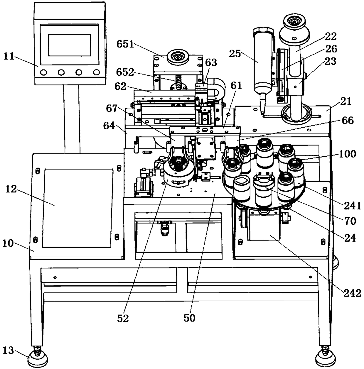
[0019] see Figure 1 to Figure 6, an automatic feeding and labeling device according to the present invention includes a workbench 10 and a control mechanism 11 arranged on the workbench, a feeding mechanism, a first labeling mechanism, a second labeling mechanism and a transfer mechanism. The feeding mechanism includes a feeding rack 21, a feeding column 22, an installation slide 23, a feeding turntable 24 and a feeding head 25. The feeding turntable 24 is located at one end of the workbench 10 , and a number of feeding stations 241 are uniformly arranged on the feeding turntable 24 . The feeding rack 21 is arranged on one side of the feeding turntable 24, the feeding column 22 is fixed on the feeding rack 21, and the installation slider 23 is s...
PUM
Abstract
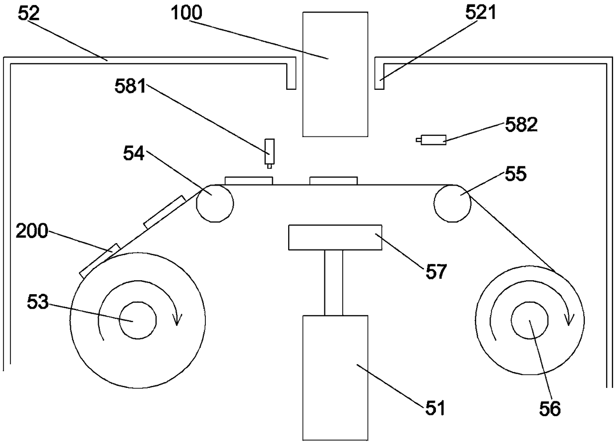
The invention discloses an automated loading and labeling device. The automated loading and labeling device comprises a working table, a control mechanism, a loading mechanism, a first labeling mechanism, a second labeling mechanism and a transferring mechanism, wherein the loading mechanism comprises a loading rack, a loading stand column, a mounting sliding block, a loading rotary table and a loading head; the second labeling mechanism comprises a feeding and conveying belt, a driving labeling rotary table, a driven labeling rotary table, a second discharging roll, a second paper collecting roll, shifting rods, an unloading plate, a first guiding plate, a second guiding plate, a U-shaped connecting piece and a pushing cylinder; the first labeling mechanism comprises a label pressing cylinder, a feeding roll, a first guiding roll, a second guiding roll, a paper collecting roll and a paper collecting motor; and the transferring mechanism comprises a transferring arm, a transverse guide track, a lead screw assembly, a sliding table, a transferring rack, a first manipulator and a second manipulator. The automated loading and labeling device is compact in structure; automatic loading, side labeling and bottom labeling of packing boxes can be finished on the device; and the automated loading and labeling device is high in degree of automation and quite convenient to use.
Description
technical field [0001] The invention relates to the field of mechanical equipment, in particular to an automatic feeding and labeling device. Background technique [0002] After the production and processing of the product is completed, it needs to be put into the packaging box, and a barcode or related label paper needs to be pasted on the packaging box. The traditional operation method is to put the product into the packaging box for packaging, and then manually transfer the packaging box to the labeling device to paste the labels one by one after the packaging is completed. The existing labeling device has a single function and can only One side of the box for label placement. The loading, packaging and labeling are done on different equipment. The whole operation is complicated, and the labor intensity of the workers is high. It needs to be transported through different conveyor belts. The equipment occupies a large area, and the production cycle of each link cannot be ...
Claims
Application Information
Patent Timeline
Application Date:The date an application was filed.
Publication Date:The date a patent or application was officially published.
First Publication Date:The earliest publication date of a patent with the same application number.
Issue Date:Publication date of the patent grant document.
PCT Entry Date:The Entry date of PCT National Phase.
Estimated Expiry Date:The statutory expiry date of a patent right according to the Patent Law, and it is the longest term of protection that the patent right can achieve without the termination of the patent right due to other reasons(Term extension factor has been taken into account ).
Invalid Date:Actual expiry date is based on effective date or publication date of legal transaction data of invalid patent.