Check patentability & draft patents in minutes with Patsnap Eureka AI!

Shift control device for automatic transmission

A technology of automatic transmission and control device, applied in the direction of transmission device, transmission device control, gear transmission device, etc., can solve the problem of increasing the load required by the actuator, and achieve the effect of lightening the load, smooth engaging action, and reducing the load.

Active Publication Date: 2019-05-03
HONDA MOTOR CO LTD
View PDF9 Cites 0 Cited by
  • Summary
  • Abstract
  • Description
  • Claims
  • Application Information

AI Technical Summary

Problems solved by technology

[0003] However, in the structure of Japanese Invention Patent Granting Publication No. 4029875, the chamfer (chamfer) 38 and the chamfer 39 are in contact, and the internal teeth and the external teeth are engaged while sliding, thereby causing The required load of the actuator required to move the sleeve 21 in the axial direction and rotate the joint sleeve 21 increases

Method used


Image

  • Shift control device for automatic transmission
  • Shift control device for automatic transmission
  • Shift control device for automatic transmission

Examples


Embodiment approach

[0051] Hereinafter, embodiments of the present invention will be described in detail with examples. However, the constituent elements described in this embodiment are merely examples, and the technical scope of the present invention is defined by the claims, and are not limited by the following individual embodiments.

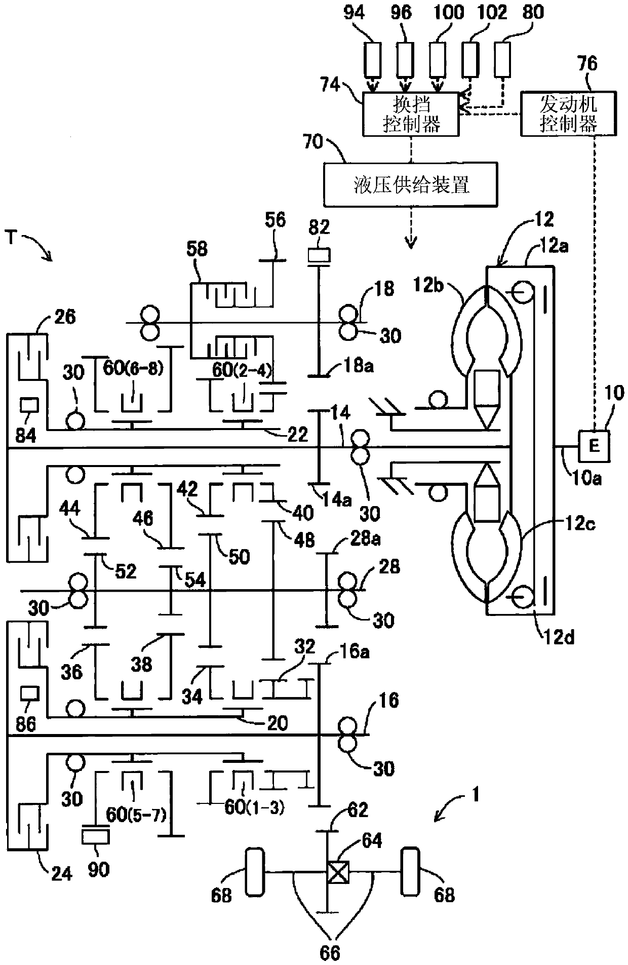
[0052] A shift control device for an automatic transmission according to an embodiment of the present invention will be described. figure 1 It is a figure which shows the schematic structure of the automatic transmission concerning embodiment. exist figure 1 In , reference sign T denotes a transmission. As the transmission T, a dual-clutch type transmission having eight forward speeds and one reverse speed, which is mounted on the vehicle 1 , is taken as an example. The transmission T has gears of D, P, R, and N.

[0053] The transmission T is connected to a drive shaft 10 a of an engine (prime mover: E) 10 through a torque converter 12 , wherein the drive ...


PUM


Abstract

An automatic transmission control device for automatic transmission is formed to make the input shaft rotary transmission and output to the output shaft. The transmission control device has: input detection department, which detects the actual rotation of the input shaft;The actual rotation of the output shaft; the presumption department, through the actual rotation of the output shaft multiplied by the target transmission ratio to correct the input shaft corresponding to the input shaft;The result to control the rotation of the input shaft.The control department controls the rotation of the input shaft, so that the upper limit of the deviation of the actual rotation of the input shaft is lower than that of the positive rotation.

Description

technical field [0001] The invention relates to a speed change control device of an automatic transmission. Background technique [0002] Japanese Patent Application Laid-Open No. 4029875 discloses a structure of a vehicle control device for controlling engagement of dog clutches during gear shifting. In this structure, the internal teeth and the external teeth are brought into engagement by simultaneously performing the control to move the sleeve 21 in the axial direction and the control to rotate the sleeve 21 . [0003] However, in the structure of Japanese Invention Patent Granting Publication No. 4029875, the chamfer (chamfer) 38 and the chamfer 39 are in contact, and the internal teeth and the external teeth are engaged while sliding, thereby causing The sleeve 21 moves in the axial direction and the required load of the actuator required to engage the sleeve 21 to rotate increases. Contents of the invention [0004] In view of the above-mentioned technical problem...

Claims


Application Information

Patent Timeline
Patent Type & Authority Patents(China)
IPC IPC(8): F16H59/46F16H3/12
CPCF16H3/12F16H59/46F16H2059/462F16D23/06F16D2023/0668F16D2023/0693F16H2061/0474F16H63/3023F16H2059/6815F16D11/14F16D23/02F16D2011/002F16D2011/008F16H3/091F16H59/40F16H59/42F16H59/68F16H61/0204F16H2063/3096
Inventor 松井洋树政冈泰行山下哲濑户佑香里伊贺上聪
Owner HONDA MOTOR CO LTD
Features
  • R&D
  • Intellectual Property
  • Life Sciences
  • Materials
  • Tech Scout
  • Unparalleled Data Quality
  • Higher Quality Content
  • 60% Fewer Hallucinations
Learn More