
Time point identification method, time point identification circuit system and laser ranging system

A one-way, voltage value technology, applied in the field of laser distance measurement, can solve problems affecting the application range and measurement accuracy of three-dimensional laser radar, and achieve the effects of saving digital-to-analog conversion time, improving measurement accuracy, and enhancing adaptability

Active Publication Date: 2020-12-04
TANWAY TECH (BEIJING) CO LTD
View PDF8 Cites 0 Cited by
  • Summary
  • Abstract
  • Description
  • Claims
  • Application Information

AI Technical Summary

Problems solved by technology

For the pulse laser radar with a laser pulse width of 5 to 10 nanoseconds, judging the arrival time of the echo pulse by a constant level will cause a nanosecond-level time measurement error, that is, a distance measurement error of tens of centimeters, which seriously affects the three-dimensional laser. Application Range and Measurement Accuracy of Radar

Method used


Image

  • Time point identification method, time point identification circuit system and laser ranging system
  • Time point identification method, time point identification circuit system and laser ranging system
  • Time point identification method, time point identification circuit system and laser ranging system

Examples


Embodiment Construction

[0014] The present invention will be described in detail below in conjunction with the accompanying drawings. However, it should be understood that the accompanying drawings are provided only for better understanding of the present invention, and they should not be construed as limiting the present invention. In the description of the present invention, it should be understood that the terms "first", "second" and so on are only used for the purpose of description, and should not be understood as indicating or implying relative importance.

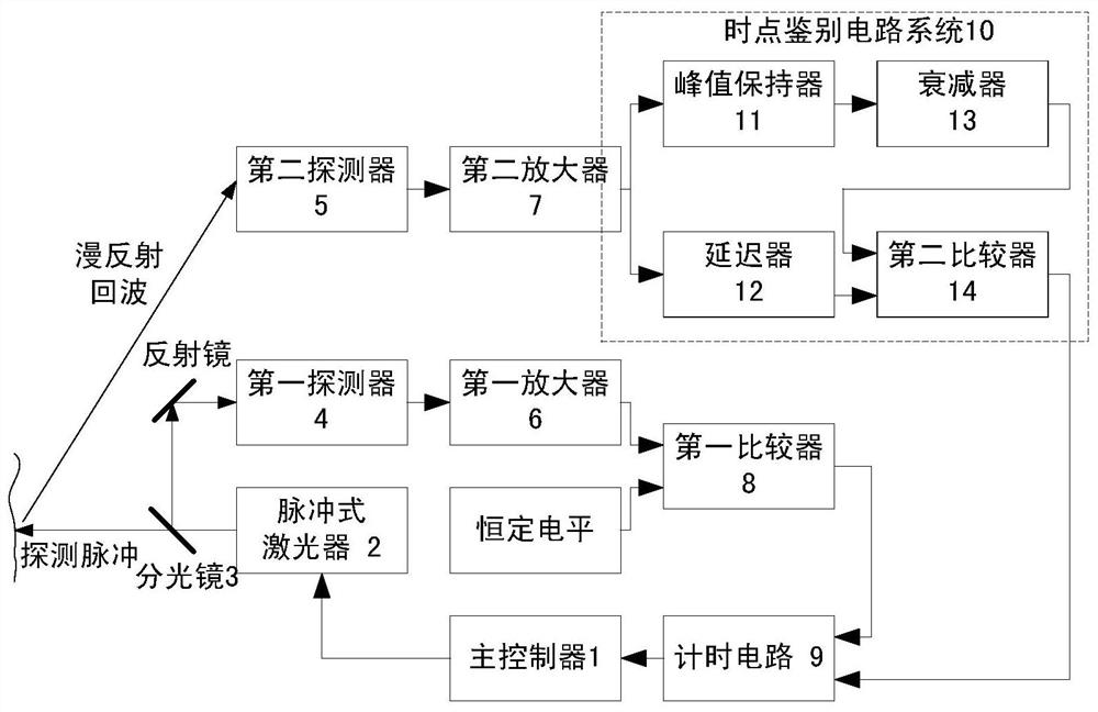
[0015] According to the principle of time-of-flight pulsed three-dimensional laser radar, the core of three-dimensional laser ranging is a pulsed ranging system based on time-of-flight method, so the time point identification method proposed by the present invention is also applicable to pulsed laser ranging system , or 2D or 3D lidar systems based on different beam scanning methods.

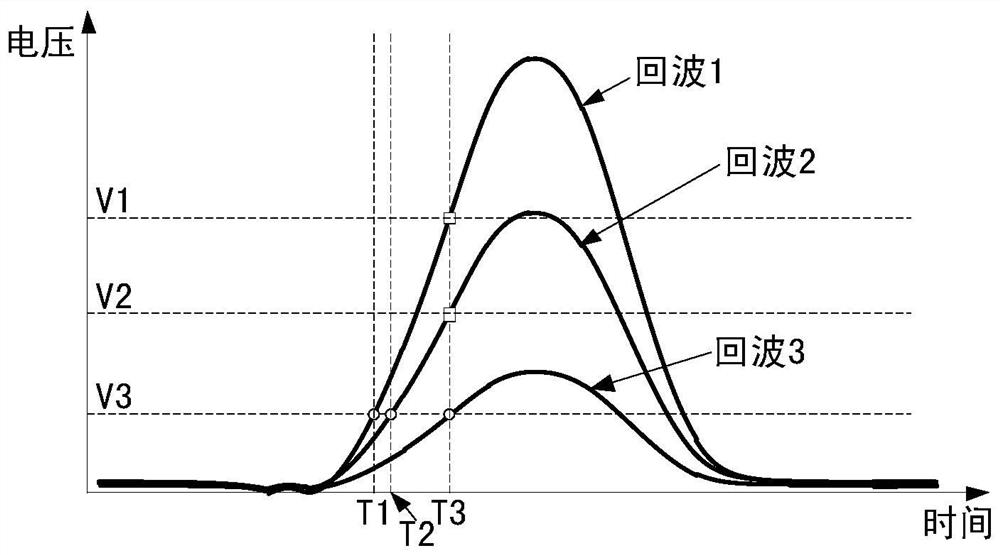
[0016] Such as figure 1 As shown, the three echoes wi...


PUM


Abstract

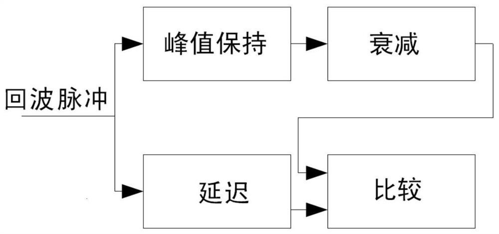
The invention relates to a time point discrimination method, a time point discrimination system and a laser ranging system. The time point discrimination method is characterized in that echo pulses detected during measurement are divided into two parts; the peak of one part of pulses is maintained, peak maintenance processing is used to convert the echo pulses into a DC level, the voltage value of the DC level is the peak voltage of the echo pulses, and the DC level is attenuated at a set proportion; the other part of pulses is delayed, delay processing is used to delay the echo pulses by nanoseconds, and the delay should be greater than the time delay caused by peak maintenance and attenuation; and the voltage value of the DC level after attenuation and the voltage value of the echo pulses after delay are compared, the moment when the voltage value comparison result changes is taken as the arrival time of echo pulses, and when the amplitude of echo pulses changes, the voltage value of the time point discrimination level changes, and thus, time point discrimination independent of echo intensity is realized. The time point discrimination method is widely used in ranging of pulsed laser ranging systems or of 2D or 3D laser radar systems based on different beam scanning modes.

Description

technical field [0001] The invention relates to a time point identification method, a time point identification circuit system and a laser distance measurement system for a pulsed laser ranging system, or a two-dimensional or three-dimensional laser radar system based on different beam scanning modes, belonging to laser distance measurement technology field. Background technique [0002] The pulsed 3D lidar based on the time-of-flight method uses a pulsed laser as the light source, which has the characteristics of long measurement distance, high frequency, and low power consumption. It is widely used in 3D modeling, environmental perception and other fields. The time-of-flight pulsed three-dimensional laser radar records the time difference ΔT between the laser pulse emission time and the diffuse echo pulse reception time, multiplied by the speed of light C, and the round-trip distance between the laser radar and the measured object can be calculated. By scanning the beam i...

Claims


Application Information

Patent Timeline
Patent Type & Authority Patents(China)
IPC IPC(8): G01S17/32G01S7/48
CPCG01S17/32
Inventor 吴冠豪
Owner TANWAY TECH (BEIJING) CO LTD
Learn More