Flight route setting method and device
A flight route and flight route technology, applied in the field of flight route setting methods and devices, can solve problems such as low efficiency and human resource consumption, and achieve the effect of reducing the number and difficulty of field operations
- Summary
- Abstract
- Description
- Claims
- Application Information
AI Technical Summary
Problems solved by technology
Method used
Image

Examples
no. 1 example
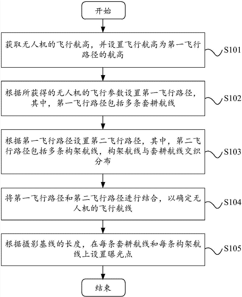
[0030] Please refer to figure 2 , figure 2 It shows the flow chart of the flight route setting method provided by the preferred embodiment of the present invention. The flight route setting method is applied to unmanned aerial vehicle aerial photography, and it comprises the following steps:
[0031] Step S101, obtaining the flying altitude of the drone, and setting the flying altitude as the flying altitude of the first flight path.
[0032] In the embodiment of the present invention, the flying height of the UAV can be the height of the UAV flying from the ground, which can be calculated by the following calculation formula:
[0033] Among them, H is the flight altitude, GSD is the ground resolution, f is the focal length of the camera, and a is the pixel size of the camera CCD (Charge-coupled Device, charge-coupled device). The flying altitude is in meters, and in actual use, use 2 digits after the decimal point, that is, it is accurate to millimeters. It should be n...
Embodiment approach
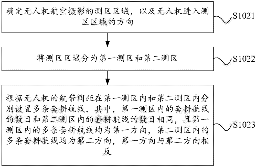
[0051] Please refer to Figure 4 , Figure 4 The laying diagram of the intertillage route provided for the first embodiment of the present invention, as an implementation mode, divides the survey area into the first survey area and the second survey area, and in the first survey area and the second survey area, respectively Set up the same number (for example, 4) intercropping routes, and the distance between any two adjacent intercropping routes is the flight belt spacing of the drone. It can be set that the multiple intertillage routes in the first survey area are all in the first direction, and the multiple intertillage routes in the second survey area are all in the second direction. The first direction is opposite to the second direction. For example, the first direction is to the right, the second direction is to the left. exist Figure 4 In the laying diagram of the intertillage route, the flying direction of the UAV is to fly along the intertillage route in the orde...
no. 2 example
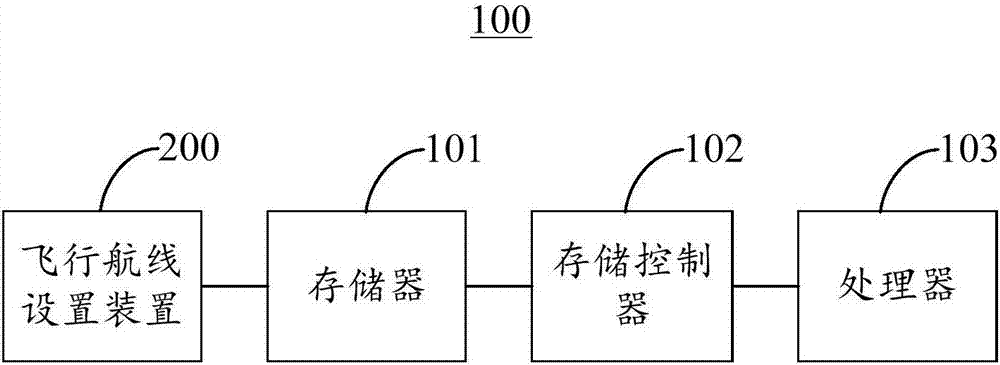
[0082] Please refer to Figure 8 , Figure 8 A schematic block diagram of the flight path setting device 200 provided by the preferred embodiment of the present invention is shown. The flight path setting device 200 includes a flight altitude acquisition module 201 , a first flight path setting module 202 , a second flight path setting module 203 , a flight path determination module 204 and an exposure point setting module 205 .
[0083] The flight altitude acquiring module 201 is configured to acquire the flight altitude of the UAV, and set the flight altitude as the altitude of the first flight path.
[0084] In the embodiment of the present invention, the flight height acquisition module 201 may be used to execute step S101.
[0085] The first flight path setting module 202 is configured to set a first flight path according to the obtained flight parameters of the UAV, wherein the first flight path includes a plurality of intertillage routes.
[0086] In the embodiment o...
PUM
 Abstract
Description
Claims
Application Information
 - Generate Ideas
- Intellectual Property
- Life Sciences
- Materials
- Tech Scout
- Unparalleled Data Quality
- Higher Quality Content
- 60% Fewer Hallucinations
Browse by: Latest US Patents, China's latest patents, Technical Efficacy Thesaurus, Application Domain, Technology Topic, Popular Technical Reports.
© 2025 PatSnap. All rights reserved.Legal|Privacy policy|Modern Slavery Act Transparency Statement|Sitemap|About US| Contact US: help@patsnap.com