
A design method of internal flow channel of cooling plate based on streamline

A design method and cooling plate technology, applied in calculation, instrumentation, geometric CAD, etc., can solve problems such as dependence, achieve the effects of reducing design experience requirements, improving flexibility, and shortening the design cycle

Active Publication Date: 2019-09-06
ZHEJIANG UNIV
View PDF4 Cites 0 Cited by
  • Summary
  • Abstract
  • Description
  • Claims
  • Application Information

AI Technical Summary

Problems solved by technology

In the previous design process, most of the premise was to meet the heat dissipation requirements, and only put forward a rough limit on the resistance. This design method largely relied on the designer's work experience

Method used


Image

  • A design method of internal flow channel of cooling plate based on streamline
  • A design method of internal flow channel of cooling plate based on streamline
  • A design method of internal flow channel of cooling plate based on streamline

Examples


Embodiment

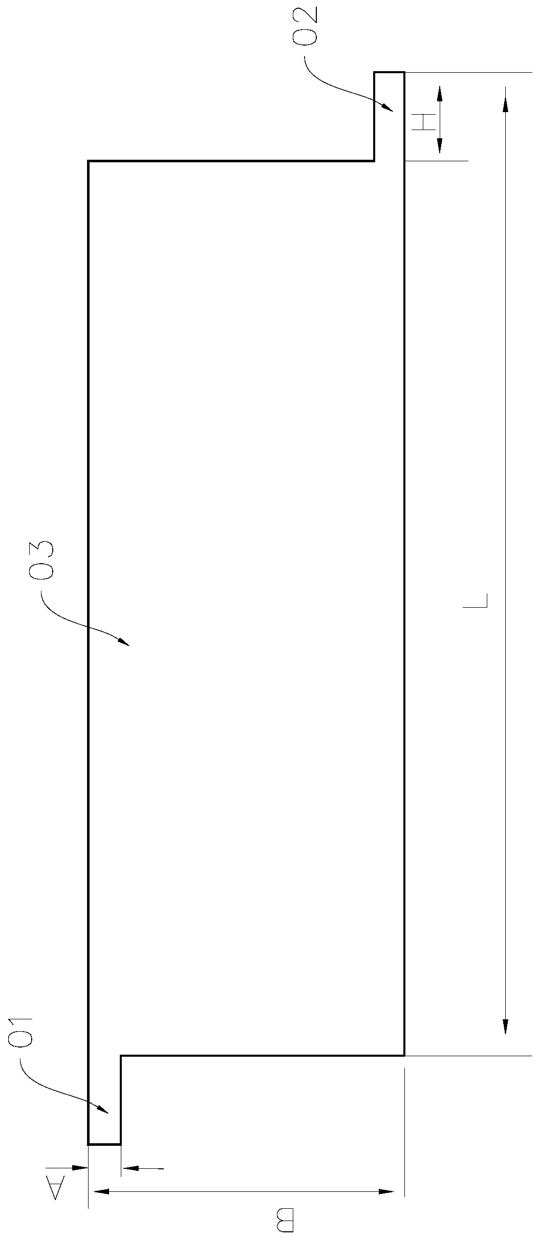
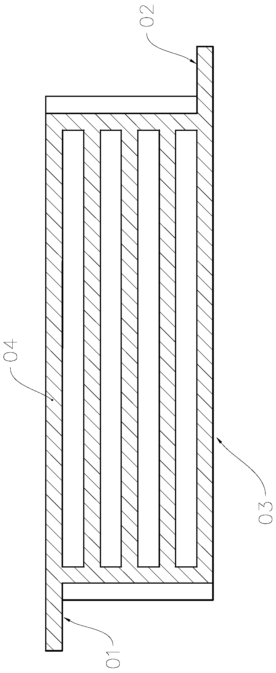
[0027] see Figure 5 , The method for designing the internal flow channel of the cooling plate based on streamlines in the present invention includes a modeling step S11, a calculating step S12, a selecting step S21 and a generating step S22.

[0028] Modeling step S11, constructing a two-dimensional structural model with the inlet of the flow channel, the distribution area of ​​the flow channel and the outlet of the flow channel, and determining the boundary conditions at the inlet of the flow channel and the outlet of the flow channel.

[0029] (1) if figure 1 As shown, the AUTOCAD software is used to construct a two-dimensional structural model with the runner inlet 01, the runner distribution area 02 and the runner outlet 03, that is, the thickness dimension of the cooling plate is not considered, and the specific dimensions are, L=330 mm, H= 30mm, B=100mm, A=10mm, the size of runner inlet 01 and runner outlet 03 are the same.

[0030] (2) The CFD pre-processing software...


PUM


Abstract

The invention relates to a streamline-based method for designing inner flow passages of cooling plates, and belongs to the technical field of computer aided design. The method comprises an obtaining step and a construction step, wherein the obtaining step comprises obtaining flow field distribution in a flow passage distribution area with a flow passage inlet and a flow passage outlet; and the construction step comprises constructing inner flow passages of cooling plates by taking a streamline in the flow field distribution as a criterion according to the quantity and distribution of designed flow passages. According to the method, a cooling plate inner flow passage distribution scheme with relatively small flow resistance can be designed, and the requirement for the design experiences of the designers can be reduced.

Description

technical field [0001] The invention relates to the technical field of computer-aided design, in particular to a method for designing an internal flow channel of a cooling plate based on streamlines. Background technique [0002] Using a cold plate for cooling can not only quickly take away the heat generated by the equipment, but also has high reliability and stability, making it a preferred heat dissipation device. [0003] During the working process, its internal flow channel will produce flow resistance to the movement of the coolant. If the flow resistance is too large, it will significantly increase the power consumption of the pump. Therefore, in the design process, it is usually necessary to compare multiple design schemes in order to Select the design scheme with the smallest flow resistance as the target scheme, for example, (1): According to the design working conditions, it is required to design the distribution structure of the outlet inlet 01, the outlet 02 and...

Claims


Application Information

Patent Timeline
Patent Type & Authority Patents(China)
IPC IPC(8): G06F17/50
CPCG06F30/17
Inventor 黄钰期陈卓烈梅盼黄瑞俞小莉
Owner ZHEJIANG UNIV
Learn More