Supercharge Your Innovation With Domain-Expert AI Agents!

High-voltage transformer

A transformer, high-voltage technology, applied in high-voltage/high-current switches, substations, non-enclosed substations, etc., can solve the problems of easy breakage at the connection, easy connection, power failure and leakage, etc., to avoid accidents and accidents, restrain Current, the effect of preventing leakage

Inactive Publication Date: 2017-10-20
彭伟成
View PDF4 Cites 0 Cited by
  • Summary
  • Abstract
  • Description
  • Claims
  • Application Information

AI Technical Summary

Problems solved by technology

[0004] In addition, due to the limitation of the length of the existing cables during the power transmission process, the cables need to be connected multiple times during the long-distance pulling process. Broken, resulting in power failure and leakage

Method used


Image

  • High-voltage transformer
  • High-voltage transformer

Examples


Embodiment 1

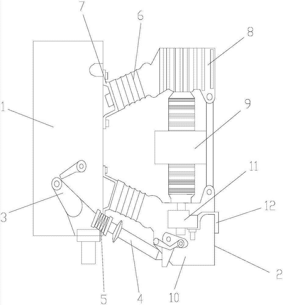
[0026] refer to figure 1 As shown, a high-voltage transformer includes a mechanism box 1 and a transformer 2. The mechanism box 1 is located on the left side of the transformer 2. The mechanism box 1 includes a swing gate 3 and a drive rod 4. The swing gate 3 Located in the mechanism box 1 , the swing gate 3 is connected with the driving rod 4 . The driving rod 4 is provided with a return spring 5, and the transformer 2 includes a supporting insulator 6, an arc extinguishing chamber 9 and a driving seat 10, and the supporting insulators 6 are respectively located below the transformer 2, and the supporting insulator 6 The upper right is provided with a fixed seat 8, the arc extinguishing chamber 9 is located inside the transformer 3, the arc extinguishing chamber 9 is connected to the fixed plate 8, the driving seat 10 is located at the bottom of the arc extinguishing chamber 9, and the driving seat 10 A conductive clip 11 is arranged inside, and a power transmission outlet 1...

Embodiment 2

[0043] refer to figure 1 As shown, a high-voltage transformer includes a mechanism box 1 and a transformer 2. The mechanism box 1 is located on the left side of the transformer 2. The mechanism box 1 includes a swing gate 3 and a drive rod 4. The swing gate 3 Located in the mechanism box 1 , the swing gate 3 is connected with the driving rod 4 . The driving rod 4 is provided with a return spring 5, and the transformer 2 includes a supporting insulator 6, an arc extinguishing chamber 9 and a driving seat 10, and the supporting insulators 6 are respectively located below the transformer 2, and the supporting insulator 6 The upper right is provided with a fixed seat 8, the arc extinguishing chamber 9 is located inside the transformer 3, the arc extinguishing chamber 9 is connected to the fixed plate 8, the driving seat 10 is located at the bottom of the arc extinguishing chamber 9, and the driving seat 10 A conductive clip 11 is arranged inside, and a power transmission outlet 1...

Embodiment 3

[0060] refer to figure 1 As shown, a high-voltage transformer includes a mechanism box 1 and a transformer 2. The mechanism box 1 is located on the left side of the transformer 2. The mechanism box 1 includes a swing gate 3 and a drive rod 4. The swing gate 3 Located in the mechanism box 1 , the swing gate 3 is connected with the driving rod 4 . The driving rod 4 is provided with a return spring 5, and the transformer 2 includes a supporting insulator 6, an arc extinguishing chamber 9 and a driving seat 10, and the supporting insulators 6 are respectively located below the transformer 2, and the supporting insulator 6 The upper right is provided with a fixed seat 8, the arc extinguishing chamber 9 is located inside the transformer 3, the arc extinguishing chamber 9 is connected to the fixed plate 8, the driving seat 10 is located at the bottom of the arc extinguishing chamber 9, and the driving seat 10 A conductive clip 11 is arranged inside, and a power transmission outlet 1...


PUM


Abstract

The invention discloses a high-voltage transformer comprising a mechanism box and a transformer. The mechanism box being arranged at the left side of the transformer consists of a swing gate and a drive lever; the swing gate is arranged in the mechanism box and is connected with the drive lever; and a reset spring is arranged at the drive lever. The transformer includes a supporting insulator, an arc extinguishing chamber and a driving base; the supporting insulator is arranged below the transformer; a fixed base is arranged at the upper right side of the supporting insulator; the supporting insulator is arranged at the inner side of the transformer and is connected with a fixed plate; the driving base is arranged at the bottom of the arc extinguishing chamber; and a conductive clamp is arranged inside the driving base and a power outlet is formed in the right side of the conductive clamp. According to the high-voltage transformer; the power transmission conversion effect is good and the current transmission can be protected.

Description

technical field [0001] The invention specifically relates to a high-voltage transformer. Background technique [0002] Wire and cable refers to materials used for power, communication and related transmission purposes. Products with fewer cores, small product diameters, and simple structures are usually called wires, those without insulation are called bare wires, and others are called cables. [0003] In my country, PVC cable materials have been successfully used as the main insulation layer of high and low voltage agricultural buried wires and industrial power cables for more than ten years. Due to the low insulation resistance and large leakage current of PVC cable insulation materials, many There is a fault in the operation of buried wires. [0004] In addition, due to the limitation of the length of the existing cables during the power transmission process, the cables need to be connected multiple times during the long-distance pulling process. Broken, resulting in po...

Claims


Application Information

Patent Timeline
Patent Type & Authority Applications(China)
IPC IPC(8): H02B5/00C04B28/04H01B17/14H01B19/00
CPCC04B28/04C04B2111/00844C04B2111/28C04B2111/92H01B17/14H01B17/145H01B19/00H01H33/42H01H33/53H01H33/72H02B5/00H02B13/025C04B14/42C04B14/46C04B14/36C04B18/103C04B16/0633C04B22/126C04B2103/302C04B14/042C04B14/303C04B14/30C04B14/48C04B22/00C04B14/02C04B18/08C04B24/005C04B12/04C04B2103/304C04B20/0048
Inventor 彭伟成
Owner 彭伟成
Features
  • R&D
  • Intellectual Property
  • Life Sciences
  • Materials
  • Tech Scout
  • Unparalleled Data Quality
  • Higher Quality Content
  • 60% Fewer Hallucinations
Learn More