
Drawer type dust collector

A dust collector, drawer-type technology, applied in the direction of dust removal, dispersing particle filtration, cleaning methods and appliances, etc., can solve the problems of poor adaptability, affecting the overall work, dust falling into the lower chamber, etc., to achieve enhanced adaptability ability, the effect of improving the service life

Inactive Publication Date: 2017-10-24
杨文浪
View PDF0 Cites 0 Cited by
  • Summary
  • Abstract
  • Description
  • Claims
  • Application Information

AI Technical Summary

Problems solved by technology

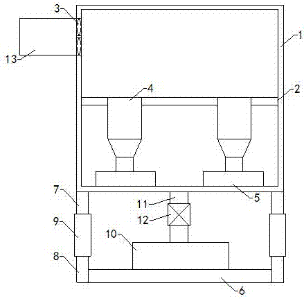
[0003] As we all know, the main purpose of the dust collector is to collect dust, which is to collect dust by using airflow and filter cartridges. It is widely used in industrial production, processing and manufacturing enterprises, and the drawer type dust collector is one of them; the existing drawer type dust collector The dust machine includes a casing, and a working chamber is arranged inside the casing, and a partition is arranged horizontally in the working chamber, which divides the working chamber into an upper chamber and a lower chamber. There is a fan, the air inlet communicates with the upper chamber, the lower chamber is provided with a filter bucket, and the outer shell is provided with a dust collection drawer, the dust collection drawer is located under the filter bucket, and the filter bucket is connected with the upper chamber; this drawer type collection During the use of the dust machine, it was found that it cannot be adjusted in height according to the requirements of the working environment, resulting in poor adaptability; and after the filter bucket is filtered and the dust is poured into the dust drawer, the dust often falls into the lower chamber. status, thereby affecting the overall work

Method used


Image

  • Drawer type dust collector

Examples


Embodiment Construction

[0010] The specific implementation manners of the present invention will be further described in detail below in conjunction with the accompanying drawings and embodiments. The following examples are used to illustrate the present invention, but are not intended to limit the scope of the present invention.

[0011] Such as figure 1 As shown, a drawer-type dust collector of the present invention includes a casing 1, a working chamber is arranged inside the casing, and a partition 2 is arranged transversely in the working chamber to divide the working chamber into an upper chamber and a lower chamber. , the casing is provided with an air inlet, and a fan 3 is arranged on the air inlet, the air inlet communicates with the upper chamber, the lower chamber is provided with a filter bucket 4, and the casing is provided with a dust collection drawer 5, the dust collection drawer is located in the filter bucket bottom, and the filter bucket communicates with the upper chamber; also i...


PUM


Abstract

The invention relates to the technical field of dust collecting devices, in particular to a drawer type dust collector. The height of the drawer type dust collector disclosed by the invention can be adjusted, and dust in a lower chamber can be better cleaned; the type dust collector comprises a housing, wherein a working chamber is arranged inside the housing, and a baffle plate is transversely arranged in the working chamber, the working chamber is divided into an upper chamber and the lower chamber, an air inlet is formed in the housing, a fan is arranged on the air inlet, filtering barrels are arranged in the lower chamber, dust collecting drawers are arranged on the housing, and the filtering barrel are communicated with the upper chamber; the drawer type dust collector further comprises a bottom plate, a left upper bracket, a left lower bracket, a right upper bracket, a right lower bracket, a left adjusting tube and a right adjusting tube; a dust collecting box is arranged at the top end of the bottom plate. The drawer type dust collector further comprises a communicating pipe, and a control pump is arranged on the communicating pipe.

Description

[0001] technical field [0002] The invention relates to the technical field of dust collecting devices, in particular to a drawer type dust collecting machine. Background technique [0003] As we all know, the main purpose of the dust collector is to collect dust, which is to collect dust by using airflow and filter cartridges. It is widely used in industrial production, processing and manufacturing enterprises, and the drawer type dust collector is one of them; the existing drawer type dust collector The dust machine includes a casing, and a working chamber is arranged inside the casing, and a partition is arranged horizontally in the working chamber, which divides the working chamber into an upper chamber and a lower chamber. There is a fan, the air inlet communicates with the upper chamber, the lower chamber is provided with a filter bucket, and the outer shell is provided with a dust collection drawer, the dust collection drawer is located under the filter bucket, an...

Claims


Application Information

Patent Timeline
Patent Type & Authority Applications(China)
IPC IPC(8): B01D46/24B08B15/00
CPCB01D46/2411B01D2267/30B01D46/58
Inventor 杨文浪
Owner 杨文浪
Learn More