
Round tube punching die

A punching and round tube technology, applied in the direction of punching tools, manufacturing tools, metal processing equipment, etc., can solve the problems of punching efficiency reduction, error, etc., and achieve the effect of reducing the time for positioning the punching position

Pending Publication Date: 2017-10-24
ZHANGJIAGANG HUATAI STAINLESS STEEL PROD
View PDF6 Cites 4 Cited by
  • Summary
  • Abstract
  • Description
  • Claims
  • Application Information

AI Technical Summary

Problems solved by technology

[0002] Usually, the punching position on the round tube is determined by the manual measurement of the worker. The manual measurement of the worker to determine the punching position has the following disadvantages: (1) Each round tube needs to be manually measured to determine the punching position, so that the punching The efficiency is greatly reduced; (2) There is often a large error between the punching position obtained by manual measurement and the actual punching position

Method used


Image

  • Round tube punching die
  • Round tube punching die
  • Round tube punching die

Examples


Embodiment Construction

[0016] The present invention will be further described in detail below in conjunction with specific embodiments and accompanying drawings.

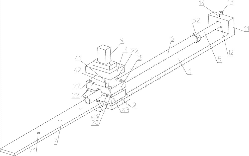
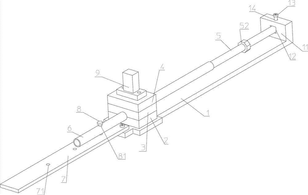
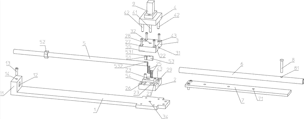
[0017] Such as figure 1 , figure 2 , image 3 , Figure 4 As shown, the round pipe punching die includes: a base 1, on which a lower mold base 2 is arranged. In this embodiment, the lower mold base 2 is detachably installed on the base 1 by bolts, 2 is provided with an upper mold base 3 that can be matched with the lower mold base 2, and a vertically arranged guide column 21 is respectively provided on the left and right sides of the upper surface of the lower mold base 2. On the upper mold base 3, there are two A guide through hole 22 that can be used for each guide post 21 to be vertically inserted one-to-one and can guide the inserted guide post 21, each guide post 21 is vertically inserted into the corresponding guide through hole 22 respectively but will not Extend out the guide through hole 22, so that the upper mold base 3 can...


PUM


Abstract

The invention discloses a round tube punching die. The round tube punching die comprises a base, a lower die base is arranged on the base, an upper die base is arranged over the lower die base, the lower die base and the upper die base are provided with guiding columns and guiding through holes respectively and provided with lower spring holes and upper spring holes respectively, and jacking springs are arranged between the upper spring holes and the lower spring holes which are oppositely formed; the lower die base is provided with limiting threaded holes, the upper die base is provided with limiting countersunk through holes, and limiting bolts penetrate through the limiting countersunk through holes and are screwed into the limiting threaded holes; the lower die base is provided with a lower arc-shaped through groove, and the upper die base is provided with an upper arc-shaped through groove; an installing table is arranged behind the lower die base, a positioning round rod provided with a positioning nut in a screwing mode is arranged between the installing table and the lower die base, a clearance hole is formed in the front end of the positioning round rod, and a first vertical through hole, a second vertical through hole and a third vertical through hole are formed in the upper arc-shaped through groove, the lower arc-shaped through groove and the base respectively; a pressing plate with a punching needle is arranged over the upper die base, a punching positioning plate is arranged in front of the lower die base, and the round tube punching die further comprises a plug pin. According to the die, a round tube can be quickly and accurately punched.

Description

technical field [0001] The invention relates to the field of round pipe processing dies, in particular to a round pipe punching die. Background technique [0002] Usually, the punching position on the round tube is determined by the manual measurement of the worker. The manual measurement of the worker to determine the punching position has the following disadvantages: (1) Each round tube needs to be manually measured to determine the punching position, so that the punching The efficiency is greatly reduced; (2) There is often a large error between the punching position obtained by manual measurement and the actual punching position. Contents of the invention [0003] The technical problem to be solved by the invention is to provide a round pipe punching die capable of punching round pipes quickly and accurately. [0004] In order to solve the above-mentioned problems, the technical solution adopted in the present invention is: a circular tube punching die, including: a b...

Claims


Application Information

Patent Timeline
IPC IPC(8): B21D28/28B21D28/34B21D43/00
CPCB21D28/28B21D28/34B21D43/003
Inventor 孙跃忠
Owner ZHANGJIAGANG HUATAI STAINLESS STEEL PROD
Learn More