Energy gradient utilization type hydrogen thermal compression system

A thermal compression, cascaded technology, applied in the field of power equipment, can solve the problems of low compression efficiency and achieve the effect of improving thermal efficiency, increasing range and selectivity

Active Publication Date: 2017-10-24
SHIJIAZHUANG XINHUA IND FURNACE CO LTD
View PDF4 Cites 18 Cited by
  • Summary
  • Abstract
  • Description
  • Claims
  • Application Information

AI Technical Summary

Benefits of technology

This patented technology provides two types of systems for effectively handling large amounts of excessive temperature swings from one type of refrigeration machine (heat pump) used on another type of material being processed or stored. These systems are designed differently depending upon how much work it performs compared against what other machines they were previously installed without affecting their performance significantly over time. By doing this, these technologies help improve the overall effectiveness of the process by allowing more efficient usage of wasted resources like fuel while also reducing environmental concerns associated therewith.

Problems solved by technology

Technological Problem: Current methods for compressing high pressure hydrogen have limitations such as poor performance at higher temperatures due to heat transfer from one stage to another during operation (which can lead to reduced reliability). Additionally, current method requires multiple stages of compression resulting in lower efficiencies than desired.

Method used


Image

  • Energy gradient utilization type hydrogen thermal compression system
  • Energy gradient utilization type hydrogen thermal compression system
  • Energy gradient utilization type hydrogen thermal compression system

Examples


Embodiment 1

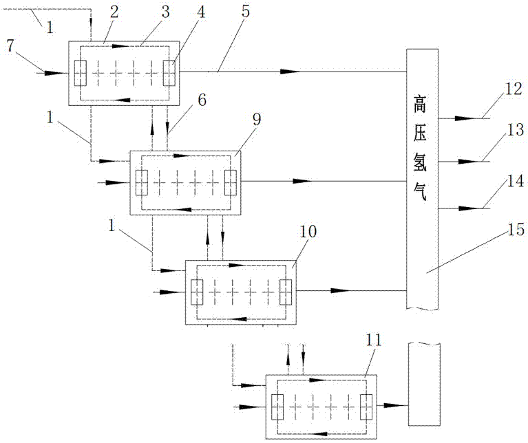
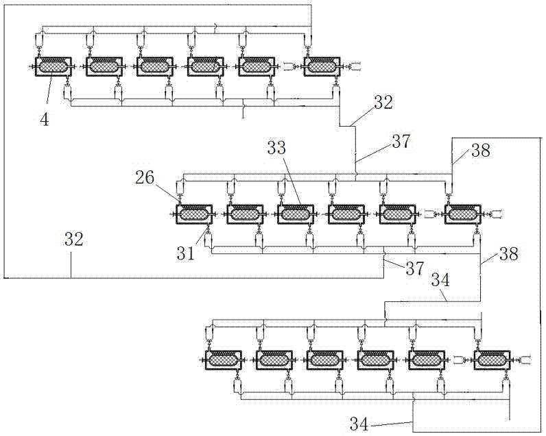
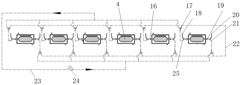
[0026] The hydrogen heat compression system of energy cascade utilization of the present invention is as figure 1 As shown, it includes a six-stage hydrogen thermal compressor and a high-pressure hydrogen main pipe 15, and the hydrogen thermal compressor is provided with a low-pressure hydrogen inlet and a high-pressure hydrogen outlet, such as figure 2 , image 3 As shown, each hydrogen thermal compressor is provided with six metal hydride reaction beds 4 . The low-pressure hydrogen inlet is connected to the low-pressure hydrogen pipeline 7, and the high-pressure hydrogen outlet is connected to the high-pressure hydrogen main pipe through the high-pressure hydrogen pipeline 5. The first-stage hydrogen heat compressor 2 is connected to the external heat source through the heat source cascade utilization pipeline 1, the first-stage hydrogen heat compressor is connected to the second-stage hydrogen heat compressor through the heat source cascade utilization pipeline 1, and the...

Embodiment 2

[0036] Another embodiment of the present invention is as Figure 4 As shown, a hydrogen thermal compression system 100, a synthetic ammonia and urea production device 30, an expander 27, a generator 28, and an electrolyzed water hydrogen generator 29, the hydrogen thermal compression system includes a ten-stage hydrogen thermal compressor and a high-pressure hydrogen main pipe 15, and the hydrogen thermal The compressor is provided with a low-pressure hydrogen inlet and a high-pressure hydrogen outlet, and each hydrogen thermal compressor is provided with eight metal hydride reaction beds 4 . The synthetic ammonia and urea production device is connected to the first-stage hydrogen heat compressor 2 through the heat source cascade utilization pipeline 1, and the external heat source is provided by the synthetic ammonia and urea production device. The first-stage hydrogen thermal compressor is connected to the second-stage hydrogen thermal compressor through the heat source casc...


PUM


Abstract

The invention relates to an energy gradient utilization type hydrogen thermal compression system. The system comprises 1-100 stages of hydrogen thermal compressors located in different working temperature intervals and a high-pressure hydrogen total pipe, wherein the hydrogen thermal compressors are provided with low-pressure hydrogen inlets, high-pressure hydrogen outlets and 1-100 metal hydride reaction beds; the low-pressure hydrogen inlets are connected with a low-pressure hydrogen pipeline, and the high-pressure hydrogen outlets are connected with the high-pressure hydrogen total pipe through a high-pressure hydrogen pipeline; an external heat source sequentially passes through multiple stages of the hydrogen thermal compressors through an external heating pipeline from the high working temperature interval to the low working temperature interval; and an interstage heat exchange pipeline is arranged between each two adjacent hydrogen thermal compressors, and an inner-stage heat exchange pipeline is arranged in each stage of the hydrogen thermal compressor. According to the energy gradient utilization type hydrogen thermal compression system, by adequately utilizing reaction heat released during hydrogen absorption of the reaction beds of the hydrogen thermal compressors by virtue of metal hydride as well as sensible heat released during a cooling operation, the thermal efficiency of each hydrogen thermal compressor is improved, and the range and selectivity of waste heat utilization are expanded.

Description


Claims


Application Information

Patent Timeline
Owner SHIJIAZHUANG XINHUA IND FURNACE CO LTD
Why Eureka
Try Eureka