Control device for concrete protective layer

A control device and protective layer technology, which is applied in the direction of construction and infrastructure engineering, etc., can solve the problems of the distance change of the protective layer, affecting the installation of anchor bolt brackets, affecting the quality of concrete, etc., and achieves the effect of uniform distance

Pending Publication Date: 2017-10-24
BENXI POWER SUPPLY COMPANY OF STATE GRID LIAONINGELECTRIC POWER SUPPLY +1
View PDF4 Cites 2 Cited by
  • Summary
  • Abstract
  • Description
  • Claims
  • Application Information

AI Technical Summary

Problems solved by technology

It often causes the following impacts: the distance between the protective layer is uneven; the distance between the protective layer is not standard; the distance between the protective layer is small, and the steel bars will leak out of the column surface; When it is not firm, the steel cage will vibrate during pouring concrete and mechanical vibration, which will cause the object controlling the distance of the protective layer to move, causing the distance of the protective layer to change; once the object controlling the distance of the protective layer falls into the concrete, it will seriously affect the quality of the concrete

Method used


Image

  • Control device for concrete protective layer
  • Control device for concrete protective layer

Examples


Embodiment 1

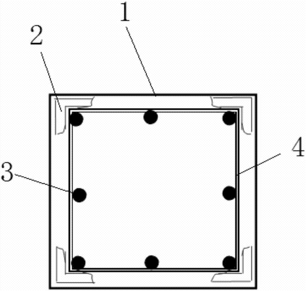
[0015] This embodiment provides a concrete protection layer control device, which is characterized in that: the concrete protection layer control device includes a reinforcement cage 1, a special wedge 2 for controlling the protection layer, a reinforcement column main reinforcement 3, and an inner formwork 4;

[0016] Among them: the reinforcement cage 1 is a cuboid columnar structure with an inner template 4 inside; the inside of the inner template 4 has a plurality of reinforcement columns and main bars 3 with a transverse spacing of 50 mm, and the four corners between the reinforcement cage 1 and the inner template 4 The position is arranged with a special wedge 2 for controlling the protective layer.

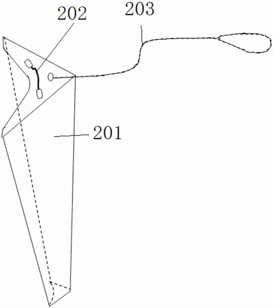
[0017] The structure of the special wedge 2 for controlling the protective layer is an angle steel shape, with a large upper and a smaller structure, including a main body 201, a wedge installation handle 202, and a wedge protection rope 203;

[0018] Wherein: the wedge ins...

Embodiment 2

[0021] This embodiment provides a concrete protection layer control device, which is characterized in that: the concrete protection layer control device includes a reinforcement cage 1, a special wedge 2 for controlling the protection layer, a reinforcement column main reinforcement 3, and an inner formwork 4;

[0022] Among them: the reinforcement cage 1 is a cuboid columnar structure with an inner template 4 inside; the inside of the inner template 4 has a plurality of reinforcement columns and main bars 3 with a transverse spacing of 150 mm, and the four corners between the reinforcement cage 1 and the inner template 4 The position is arranged with a special wedge 2 for controlling the protective layer.

[0023] The structure of the special wedge 2 for controlling the protective layer is an angle steel shape, with a large upper and a smaller structure, including a main body 201, a wedge installation handle 202, and a wedge protection rope 203;

[0024] Wherein: the wedge in...

Embodiment 3

[0027] This embodiment provides a concrete protection layer control device, which is characterized in that: the concrete protection layer control device includes a reinforcement cage 1, a special wedge 2 for controlling the protection layer, a reinforcement column main reinforcement 3, and an inner formwork 4;

[0028] Among them: the reinforcement cage 1 is a cuboid columnar structure with an inner template 4 inside; the inside of the inner template 4 has a plurality of reinforcement columns and main bars 3 with a transverse spacing of 150 mm, and the four corners between the reinforcement cage 1 and the inner template 4 The position is arranged with a special wedge 2 for controlling the protective layer.

[0029] The structure of the special wedge 2 for controlling the protective layer is an angle steel shape, with a large upper and a smaller structure, including a main body 201, a wedge installation handle 202, and a wedge protection rope 203;

[0030] Wherein: the wedge in...


PUM


Abstract

A control device for a concrete protective layer is characterized in that the control device for the concrete protective layer comprises a reinforcement cage, wedges special for controlling the protective layer, reinforcement stand column main reinforcements and an inner formwork. The reinforcement cage is of a cuboid columnar structure and is internally provided with the inner formwork, the inner formwork is internally provided with the multiple reinforcement stand column main reinforcements, and the transverse distance is 50-150 mm; and the wedges special for controlling the protective layer are arranged at the four corners between the reinforcement cage and the inner formwork. The control device has the advantages that the wedges special for controlling the protective layer can control the inner formwork and the reinforcement cage and are provided with thick upper portions and thin lower portions, and the control device achieves the following functions that the design of the standard distance over the protective layer can be ensured, the evenness of the distances of the four surfaces of the protective layer can be ensured, it can be ensured that the special wedges cannot displace and fall down in the construction process, after the special wedges are installed, the heights of the upper surfaces of the wedges cannot exceed the upper edge of a foundation formwork, and installation of a foundation bolt support cannot be affected.

Description

technical field [0001] The invention relates to the field of transmission line engineering construction facilities, in particular to a concrete protective layer control device. Background technique [0002] At present, in the foundation construction of transmission lines, there has been no special tool for controlling the distance between the foundation formwork and the protective layer of the steel cage. On site, garden wood, square wood, stones, iron bars, angle iron, etc. are generally used as pads between the formwork and the steel cage. It often causes the following impacts: the distance between the protective layer is uneven; the distance between the protective layer is not standard; the distance between the protective layer is small, and the steel bars will leak out of the column surface; When it is not firm, the steel cage will vibrate during pouring concrete and mechanical vibration, which will cause the object controlling the distance of the protective layer to mo...

Claims


Application Information

Patent Timeline
Patent Type & Authority Applications(China)
IPC IPC(8): E02D27/42
CPCE02D27/42
Inventor 王玲李鹏孙谋成杨营
Owner BENXI POWER SUPPLY COMPANY OF STATE GRID LIAONINGELECTRIC POWER SUPPLY
Why Eureka
Try Eureka