Multi-stage isochronous point noise source position reverse-time imaging method

A technology of noise source location and imaging method, applied in measurement devices, instruments, scientific instruments, etc., can solve problems such as unsatisfactory elimination effect, and achieve the effect of positioning efficiency, positioning accuracy, and good adaptability

Inactive Publication Date: 2017-10-24
JILIN UNIV
View PDF4 Cites 0 Cited by
  • Summary
  • Abstract
  • Description
  • Claims
  • Application Information

AI Technical Summary

Benefits of technology

This patented technology allows for improved methods for locating noise sources near an underground structure during exploration operations. By utilizing specific techniques like reversely timed images (RTIs) and randomly selected detectors, these technologies can improve their effectiveness while reducing errors caused by environmental factors such as ground movements. Additionally, they allow for better control over both spatial resolution and depth penetration through the use of coherence tomography (CT). Overall, this innovative technique helps identify potential oil reserves accurately without relying solely upon traditional means.

Problems solved by technology

This patents discusses techniques related to sound prospecting technology. These technologies aim at identifying specific sounds or events within space without relying solely upon physical laws like acoustic emission signatures. They rely heavily on recording small amounts of signal samples over time rather than directly measuring them themselves. To address this issue, they propose new ways to detect and identify certain types of noisy phenomena - including reflection tomography, inverse delay imprint technique, and reverberant sonar imaging systems.

Method used


Image

  • Multi-stage isochronous point noise source position reverse-time imaging method
  • Multi-stage isochronous point noise source position reverse-time imaging method
  • Multi-stage isochronous point noise source position reverse-time imaging method

Examples


Embodiment 1

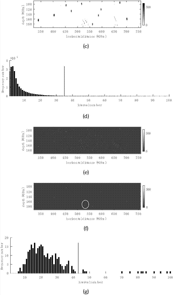
[0085] a. Input the noise record and underground velocity model; adopt a uniform model of 1043*302, the grid spacing is 10m, and 522 detection points are evenly distributed on the surface; the excitation of all noise sources is 0-1000ms, and different random sequences and 30Hz mine The convolution of the Kelet wavelet is used as the wavelet; the time sampling interval is 1ms, the duration of the noise source is 3000-4000ms, and the total recording time is 4000ms; the source distribution is 10 sources scattered in a uniform medium of 3000m / s ( Figure 6 (a));

[0086] b. Using the conventional reverse time imaging method to obtain the original imaging results, using a mixed imaging condition

[0087]

[0088] As the imaging condition, where, I l (x)(l∈Z + ) represents the imaging value at spatial position x, R i (x,t) represents the wave field value from the ith detection point at the spatial position x and the backpropagation time t, G is the number of detection point gr...

Embodiment 2

[0098] a. Input the noise record and underground velocity model; adopt a uniform model of 1043*302, the grid spacing is 10m, and 522 detection points are evenly distributed on the surface; the excitation of all noise sources is 0-1000ms, and different random sequences and 30Hz mine The convolution of the Kelet wavelet is used as the wavelet; the time sampling interval is 1ms, the duration of the noise source is 3000-4000ms, and the total recording time is 4000ms; the source distribution is 10 sources scattered in a uniform medium of 3000m / s ( Figure 6 (a)); In order to test the influence of white noise on this method, white noise is added to the forward modeling record, and the record at the center detection point is extracted ( Figure 7 (a) compared with (b));

[0099] b. Using the conventional reverse time imaging method to obtain the original imaging results, using a mixed imaging condition

[0100]

[0101] As the imaging condition, where, I l (x)(l∈Z + ) represent...


PUM


Abstract

The invention relates to a multi-level isochronous point noise source position reverse-time imaging method. First, a conventional reverse-time imaging method is applied to the noise source positioning, and in combination with the statistical threshold, a conventional positioning result is obtained. Then, the local extreme points are used as a shock source; then using an Eikonal equation to calculate their first arrival time; using the wave field information of these points; and obtaining an isochronous point positioning result; and finally, the two positioning results are used for mutual reference so as to reserve the points that are identified as the shock source in both methods. The method of the invention greatly improves the effect of using the TRI method to locate a noise source in terms of both imaging accuracy and illusion suppression, and has good adaptability to the low signal-to-noise ratio data. The combination of the mixed imaging conditions and the random selection of detection points is implemented, striking a balance between the positioning efficiency and positioning accuracy; and in the final positioning result, the distribution of its illusion and the conventional positioning result are all different, which is conducive to the compare and identify the real shock source and the distribution of illusion.

Description


Claims


Application Information

Patent Timeline
Owner JILIN UNIV
Why Eureka
Try Eureka