Insulated shell with integrated function and manufacturing method thereof

A technology of insulating shell and manufacturing method, which is applied in the field of insulating shell of vacuum interrupter and its manufacturing, and can solve problems such as development constraints

Active Publication Date: 2017-10-24
BEIJING BOE VACUUM ELECTRONICS CO LTD
View PDF10 Cites 1 Cited by
  • Summary
  • Abstract
  • Description
  • Claims
  • Application Information

AI Technical Summary

Problems solved by technology

However, due to the limitations of its own structure, the existing vacuum interrupters are difficult to maintain good voltage resistance in

Method used


Image

  • Insulated shell with integrated function and manufacturing method thereof
  • Insulated shell with integrated function and manufacturing method thereof
  • Insulated shell with integrated function and manufacturing method thereof

Examples


Embodiment 1

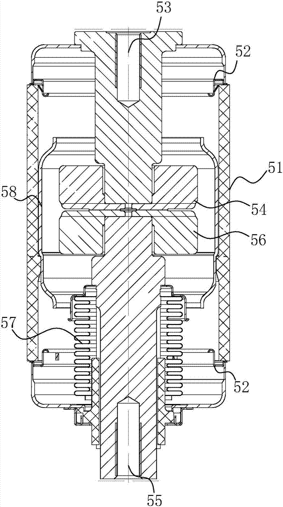
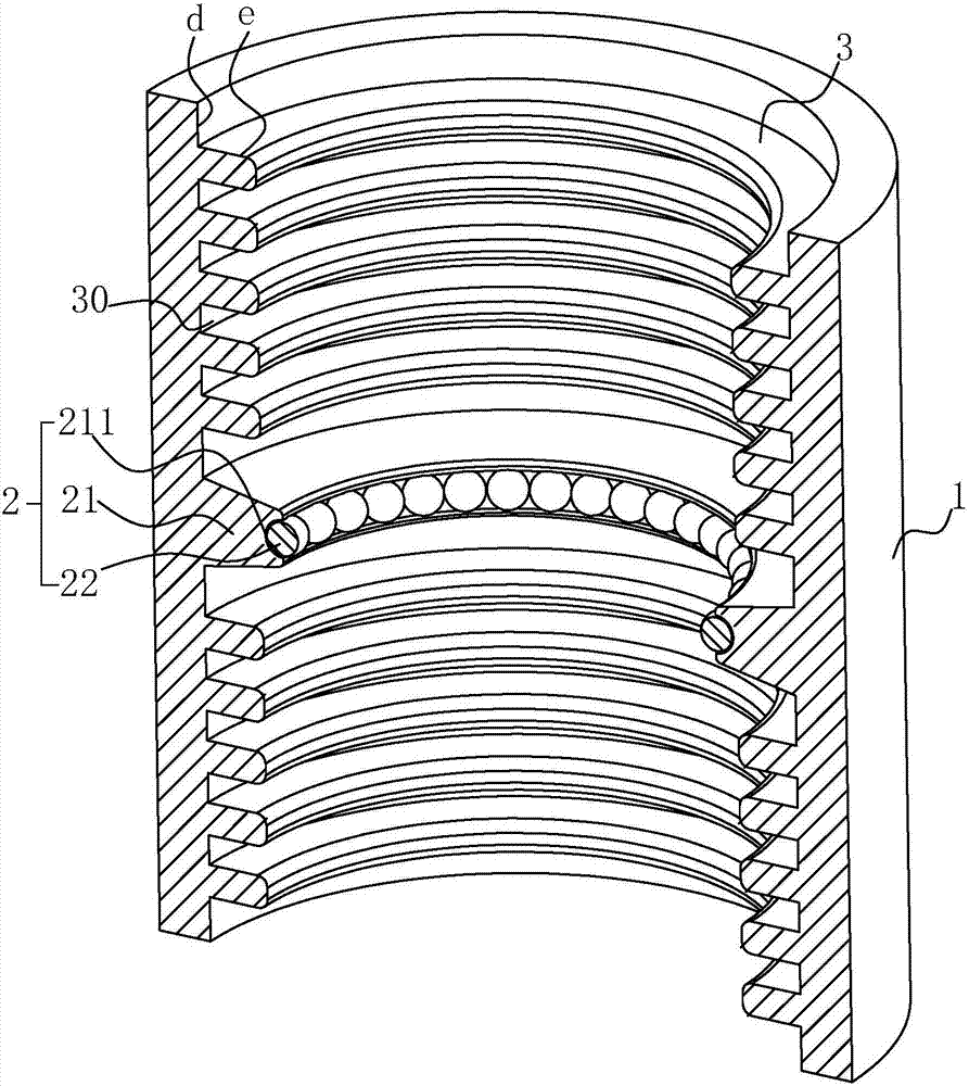
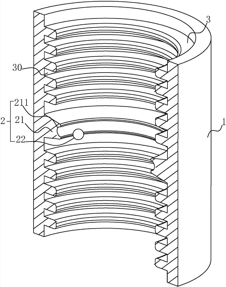
[0084] refer to figure 2 with image 3 , an insulating shell with integrated functions, including a cylindrical shell 1, where the "cylindrical" should include but not limited to three-dimensional shapes such as cylinders, spheres, ellipsoids, and spindles. Embodiment 1 uses cylinders The cylindrical shell 1 is an example, the cylindrical shell 1 can be made of glass, ceramics, glass-ceramic or plastic, and the first embodiment uses ceramic material as an example, and the openings at both ends of the cylindrical shell 1 are used to seal the metal cover plate to form a closed vacuum interrupter, figure 1 The arc pilot ring 2 located in the middle of the axial direction of the cylindrical shell 1 can be seen in the figure. The arc pilot ring 2 includes an annular mounting ring 21, and an annular fitting groove 211 is formed on the inner circumference of the mounting ring 21. The fitting groove 211 is used for To fit and connect the ball contacts 22, a plurality of ball contac...

Embodiment 2

[0090] An insulating housing with integrated functions, see Figure 5 , the difference from Embodiment 1 is that the spherical contact 22 is replaced by a columnar contact 23, and the shape selection of the contact on the arc ring 2 for attracting the arc between the contacts should be avoided as much as possible. The burrs or corners are used to reduce the impact of the contacts on the magnetic field in the vacuum interrupter and improve the voltage resistance of the vacuum interrupter. The columnar contact 23 shown in the figure has a longer length in the axial direction of the cylindrical shell 1 Length, suitable for higher voltage vacuum circuit breakers with larger spacing between contacts.

Embodiment 3

[0092] An insulating housing with integrated functions, see Image 6 The difference between it and the second embodiment is that the cylindrical contact 23 is replaced by a ring contact 24. Since the outer diameter of the ring contact 24 matches the diameter of the fitting groove 211, it is difficult to install a complete ring into the fitting Therefore, the circular contact 24 is divided into three or more equal parts, which are installed and welded in the fitting groove 211 one by one to form a complete ring.


PUM


Abstract

The invention discloses an insulated shell with an integrated function, which comprises a tubular shell. The inner wall of the tubular shell is provided with a raised or sunken uneven line for increasing the creepage distance between two axial ends of the tubular shell; the creepage distance path formed by the raised or sunken uneven line is provided with more than two climbing or detouring-type sub paths, and thus, the creepage distance is increased, and the voltage-resistance performance is enhanced; due to the construction of creepage extending rings is adopted, the creepage distance is greatly improved, pollution of the whole inner wall of the tubular shell by metal vapor evapotranspiration is avoided, due to double effects of the large creepage distance and the large pollution-free area ratio, the voltage-resistance performance and the back-arc insulation level of the insulated shell with the integrated function are greatly improved, the back-arc electrical insulation index of a vacuum interrupter does not fall, and the insulated shell with the integrated function and the vacuum interrupter is developed towards a high voltage and ultra high voltage direction.

Description

technical field [0001] The invention relates to the field of vacuum circuit breakers, in particular to an insulating shell of a vacuum interrupter in a vacuum circuit breaker and a manufacturing method thereof. Background technique [0002] The vacuum interrupter is the core component of the vacuum circuit breaker, such as figure 1 As shown, it includes a generally cylindrical insulating shell 51 made of inorganic insulating materials such as ceramics or glass. The two ends of the insulating shell 51 are sealed with metal cover plates 52 to form an airtight container. The inside of the airtight container is provided with a fixed The static contact 54 on the static conductive rod 53, and the movable contact 56 fixed on the movable conductive rod 55, the bellows 57 is sealed between the movable conductive rod 55 and the metal cover plate 52, and the movable conductive rod 55 is arranged along its axis. To move the movable contact 56 to complete the opening and closing action ...

Claims


Application Information

Patent Timeline
IPC IPC(8): H01H33/662H01H69/00
CPCH01H33/66207H01H33/12H01H33/662H01H69/00
Inventor 任建昌张坦
Owner BEIJING BOE VACUUM ELECTRONICS CO LTD
Why Eureka
Try Eureka