
Test structure, preparation method and test method for short-circuit defect of shared contact hole

A technology for sharing contact holes and short-circuit defects, which is applied in semiconductor/solid-state device testing/measurement, circuits, electrical components, etc., and can solve the problems of inaccuracy in optical inspection, failure of electrical defects, monitoring, etc.

Active Publication Date: 2019-11-22
SHANGHAI HUALI INTEGRATED CIRCUTE MFG CO LTD
View PDF4 Cites 0 Cited by
  • Summary
  • Abstract
  • Description
  • Claims
  • Application Information

AI Technical Summary

Problems solved by technology

However, for this electrical failure problem, optical inspection is not accurate enough for on-line monitoring, and since the shared contact hole is in a conventional SRAM structure, one end of it will be connected to polysilicon, when the other end is shorted to another polysilicon , there will be no change in potential, so it cannot be monitored for electrical defects, such as Figure 5 shown

Method used


Image

  • Test structure, preparation method and test method for short-circuit defect of shared contact hole
  • Test structure, preparation method and test method for short-circuit defect of shared contact hole
  • Test structure, preparation method and test method for short-circuit defect of shared contact hole

Examples


Embodiment Construction

[0040] In order to make the content of the present invention clearer and easier to understand, the content of the present invention will be further described below in conjunction with the accompanying drawings. Of course, the present invention is not limited to this specific embodiment, and general replacements known to those skilled in the art are also covered within the protection scope of the present invention.

[0041] The following is attached Figure 6-10 The present invention will be described in further detail with specific examples. It should be noted that the drawings are all in a very simplified form, using imprecise scales, and are only used to facilitate and clearly achieve the purpose of assisting in describing the present embodiment.

[0042] see Figure 6 and Figure 8 , a test structure for a short-circuit defect in a gate-source shared contact hole in this embodiment has a transistor of the first conductivity type, which is a PMOS transistor here. In this...


PUM


Abstract

The invention provides a test structure for the short-circuit defect of a shared contact hole, a preparation method and a test method. The test structure has a first conductive type transistor. The first conductive type transistor comprises an active region, a first gate and a second gate located on the active region, a first gate-source shared contact hole located on the first gate and a second gate-source shared contact hole located on one end of the second gate. The bottom of one end of the second gate is not provided with the active region. The first gate-source shared contact hole is connected with one end of the first gate and the active region. The second gate-source shared contact hole is only connected with one end of the second gate. The bottom of the second gate-source shared contact hole is not connected with the active region. According to the test structure of the invention, whether the second gate-source shared contact hole is short-circuited or not can be intuitively judged. Therefore, the monitoring over the flatness, the process and the equipment of a subsequent process window is facilitated.

Description

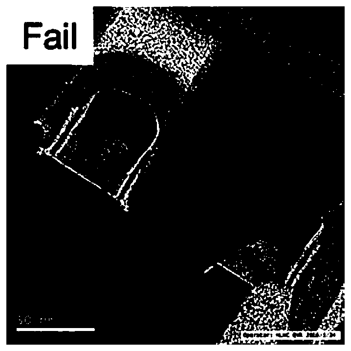
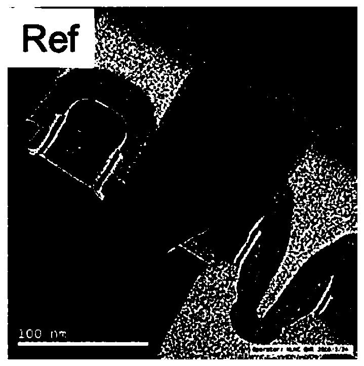
technical field [0001] The invention relates to the technical field of semiconductor manufacturing, in particular to a test structure and a test method for a short-circuit defect of a shared contact hole. Background technique [0002] With the development of integrated circuit technology, the size of semiconductor technology is getting smaller and more complex. The process window of many process integrations is getting smaller and smaller, such as the short circuit between contact holes and polysilicon, which is affected by alignment accuracy and critical dimensions of contact holes and polysilicon, and is one of the difficult issues in the development of processes below 28nm. [0003] Such as Figures 1 to 5 As shown, among them, figure 1 It is a schematic diagram of wafer yield test, figure 2 A scanning electron microscope picture of a short circuit between the existing gate-source shared contact hole and the gate, image 3 A scanning electron microscope picture of th...

Claims


Application Information

Patent Timeline
Patent Type & Authority Patents(China)
IPC IPC(8): H01L21/66
CPCH01L22/30H01L22/32
Inventor 范荣伟陈宏璘龙吟王恺
Owner SHANGHAI HUALI INTEGRATED CIRCUTE MFG CO LTD
Learn More