Method and device for signal transmission

A signal transmission and signal technology, applied in the field of communication, can solve problems such as difficult to support low-latency services

Active Publication Date: 2017-10-24
ZTE CORP
View PDF8 Cites 5 Cited by
  • Summary
  • Abstract
  • Description
  • Claims
  • Application Information

AI Technical Summary

Problems solved by technology

Generally speaking, due to the overhead of the frame structure, the longer the basic resource unit, the smaller the ove

Method used


Image

  • Method and device for signal transmission
  • Method and device for signal transmission
  • Method and device for signal transmission

Examples


Embodiment 1

[0358] see Figure 4 , the present invention proposes a signal transmission method, the method comprising:

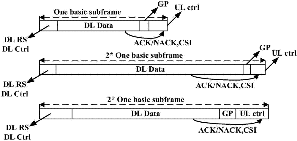
[0359] In this example, the combination order of subframes is subframe 1, subframe 2, and subframe 3, where subframe 1 is a short TTI, subframe 2 and subframe 3 are long TTIs; where a short TTI includes a BRU, and a short TTI The feedback of the TTI follows the timing of n+2; the long TTI includes four BRUs, and the feedback follows the timing of n+1, where n=1 and 2 are both length units relative to the TTI type.

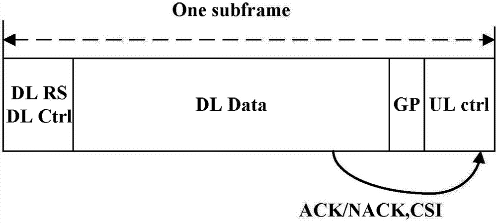
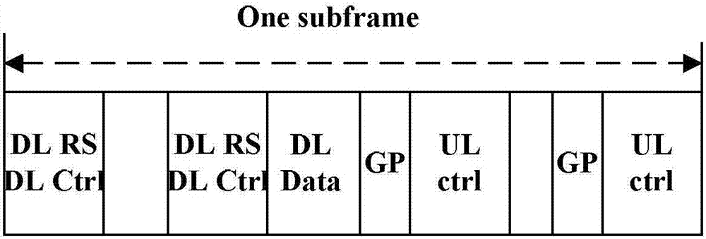
[0360] Each TTI includes a DC (downlink control) area, a Data (data) area and a UC (uplink control) area. Wherein, Data may be an uplink data area or a downlink data area.

[0361] Step 410, the terminal receives DL Control and DL data that need to be fed back in the Data area of ​​subframe 1;

[0362] According to the preset feedback mechanism, the terminal needs to send feedback signals corresponding to DL Control and DL data that need to be fed back in...

Embodiment 2

[0397] In this embodiment, another multiplexing solution in which long and short subframe TTIs belong to the same user is introduced.

[0398] There may also be a possible solution to the mixture of long and short subframes, that is, the long TTI transmits the control information that needs to be fed back in the short TTI, and needs to be multiplexed with other feedback information of the short TTI. Such as Figure 7 As shown, the long TTI is followed by 4 short TTIs. According to the feedback timing of the long TTI n+1, the feedback is falling into the uplink time slot of the fourth short TTI, which needs to be multiplexed with the uplink control information originally undertaken by the short TTI. .

Embodiment 3

[0400] In this embodiment, a solution that the long and short subframe TTIs do not belong to the same user is introduced.

[0401] In the case that the long and short subframes belong to different users, for example, the short subframe is a low-latency Internet of Things (uMTC) user, and the long subframe is a mobile user (MBB) with general wide-area coverage. The usage is consistent with the method that the long and short subframe TTIs belong to the same user. But because the two users are separated, the terminal capabilities of the two users, such as whether they have self-feedback, cannot be directly transmitted, and the acquisition of their prior information is more complicated. When the feedback signaling of the uMTC user needs to be carried in the data part of the MBB user, and the terminal capability of the uMTC user cannot be directly transmitted to the MBB user, it needs to be conveyed by the base station. The base station notifies the user of the allocation mode of ...


PUM


Abstract

The invention discloses a method and a device for signal transmission. The method includes the steps of determining a punching area based on a basic resource unit BRU, and transmitting signals in a non-punching area within a sub-frame. Through the scheme of the invention, a mode of transmitting a feedback signal under the condition that long and short frames are used together or other signals needing priority processing is provided. Under the condition that the law of hybrid occurrence and combination of long and short frames may be pure-dynamic or semi-static adjustment, a hole is punched at a predetermined position to get sending resources according to a preset feedback strategy. Complicated search for a feedback position is avoided, and timely sending of feedback signals is ensured. The problem of resource conflict in the existing feedback mode is solved.

Description

technical field [0001] The invention relates to the field of communication, in particular to a signal transmission method and device. Background technique [0002] The new generation of mobile communication systems will carry out system networking on carrier frequencies higher than those used by 2G, 3G, and 4G systems. Currently, the frequency bands that have been widely agreed in the industry and recognized by international organizations are mainly 3GHz~6GHz, 6GHz~100GHz. The first frequency band basically belongs to the centimeter wave band and the millimeter wave band, and its propagation characteristics are significantly different from those of the lower frequency bands. Compared with the symmetrical carrier deployment of FDD, the channel reciprocity of the TDD system is more conducive to playing a role in such high frequency bands. At the same time, the TDD mode is also beneficial to reduce the cost and system overhead of using a large-scale antenna array. Therefore, t...

Claims


Application Information

Patent Timeline
IPC IPC(8): H04W72/04H04L5/00
CPCH04L5/0048H04L5/0055H04W72/0446H04W72/20H04W72/04
Inventor 郝鹏张峻峰李剑鲁照华
Owner ZTE CORP
Why Eureka
Try Eureka