LED driving circuit and LED electrical indicating lamp

A technology of LED drive and indicator light, applied in the field of LED lighting, which can solve the problems of poor quality, change, and unbalanced adjustment of LED drive circuits, and achieve the effects of increasing safety guarantee coefficient and reliability, improving luminous quality, and reducing failure rate

Pending Publication Date: 2017-10-24
GUANGDONG UNIV OF TECH
View PDF0 Cites 1 Cited by
  • Summary
  • Abstract
  • Description
  • Claims
  • Application Information

AI Technical Summary

Problems solved by technology

The quality of LED electrical indicator lights has been improved compared to the electrical indicator lights that use filament heat as a light source. However, the LED drive circuit of the existing LED electrical indicator lights is relatively inferior, resulting in the quality and life of LED electrical indicators. Decreased significantly
[0003] Specifically, the LED drive circuit includes a plurality of LED branches, and each LED branch includes an LED string. When the LED strings in the LED branch are short-circuited or disconnected, the current flowing through the faulty LED branch will change. As a result, the current flowing through other non-faulty LED branches also changes, making the current flowing through each LED branch uneven
In view of this situation, the driving circuit in the prior art cannot balance and adjust the current flowing through each LED branch, so that the luminous quality and life of the LED electrical indicator light are affected due to the uneven current flowing through each LED branch. Increased the failure rate of LED electrical indicators, reducing the safety factor and reliability of LED electrical indicators

Method used


Image

  • LED driving circuit and LED electrical indicating lamp
  • LED driving circuit and LED electrical indicating lamp

Examples


Embodiment Construction

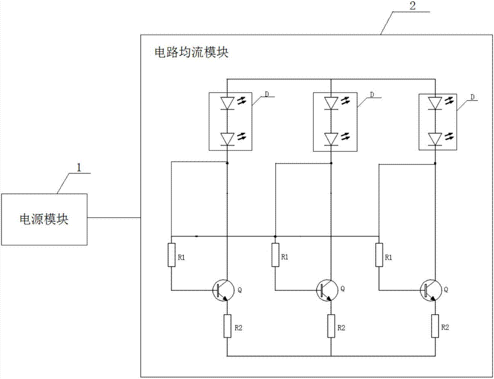
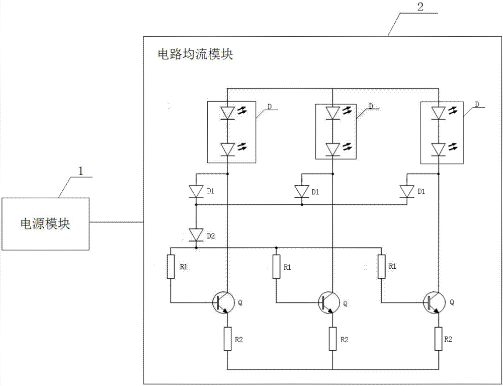
[0028] The core of the present invention is to provide an LED drive circuit and an LED electrical indicator light, which improves the luminous quality of the LED electrical indicator light, prolongs the life of the LED electrical indicator light, reduces the failure rate of the LED electrical indicator light, and increases the LED electrical indicator light. The safety factor and reliability of the indicator light.

[0029] In order to make the purpose, technical solutions and advantages of the embodiments of the present invention clearer, the technical solutions in the embodiments of the present invention will be clearly and completely described below in conjunction with the drawings in the embodiments of the present invention. Obviously, the described embodiments It is a part of embodiments of the present invention, but not all embodiments. Based on the embodiments of the present invention, all other embodiments obtained by persons of ordinary skill in the art without making...


PUM


Abstract

The invention discloses an LED driving circuit and an LED electrical indicating lamp. A power supply module and a circuit current sharing module are included. The circuit current sharing module comprises N parallel LED branches with a same specification. Each LED branch comprises an LED string, a triode, a base electrode resistor and an emitter electrode resistor. The N is an integer which is not less than 2. A first end of the LED string is connected to an output positive end of the power supply module. A second end of the LED string is connected to a first end of the base electrode resistor and a collector electrode of the triode on the branch where the LED string is located respectively. A second end of the base electrode resistor and a base electrode of the triode are connected. An emitter electrode of the triode and a first end of the emitter electrode resistor are connected. A second end of the emitter electrode resistor and an output negative end of the power supply module are connected. First ends of the base electrode resistors on the N LED branches are mutually connected. In the invention, a service life of the LED electrical indicating lamp is prolonged, a failure rate of the LED electrical indicating lamp is reduced, and reliability of the LED electrical indicating lamp is increased.

Description

technical field [0001] The invention relates to the field of LED lighting, in particular to an LED driving circuit and an LED electric indicator light. Background technique [0002] With the development of lighting technology, the application of LED electrical indicator lights is becoming more and more extensive. Compared with the electric indicator light using filament heating as the light source, the quality of the LED electrical indicator light has been improved. However, the LED drive circuit of the existing LED electrical indicator light is relatively inferior, resulting in the quality and life of the LED electrical indicator light. Decreased significantly. [0003] Specifically, the LED drive circuit includes a plurality of LED branches, and each LED branch includes an LED string. When the LED strings in the LED branch are short-circuited or disconnected, the current flowing through the faulty LED branch will change. As a result, the current flowing through other non...

Claims


Application Information

Patent Timeline
IPC IPC(8): H05B33/08F21V29/50F21Y115/10H05B44/00
CPCF21V29/50F21Y2115/10H05B45/56H05B45/375H05B45/345H05B45/52H05B45/54
Inventor 何苗许木桂王成民周海亮王润
Owner GUANGDONG UNIV OF TECH
Why Eureka
Try Eureka