Ion implanting apparatus

a technology of implanting apparatus and ion beam, which is applied in the field of ion beam implanting apparatus, can solve the problems of deteriorating the uniformity of the beam current density distribution in the width direction of the ion beam, the limit of the multi-polar ion lens, and the non-uniform distribution etc., to achieve the effect of enhancing the uniformity or parallelism, enhancing the uniformity of the beam current density distribution, and enhancing the uniformity of the beam current density

Active Publication Date: 2006-07-18
NISSIN ION EQUIP CO LTD
View PDF5 Cites 16 Cited by
  • Summary
  • Abstract
  • Description
  • Claims
  • Application Information

AI Technical Summary

Benefits of technology

[0010]In view of the above circumstance, this invention mainly intends to provide an ion implanting apparatus capable of dealing with the large-scaling of a substrate while suppressing a reduction in the uniformity of a beam current density distribution in a width direction of an ion beam, deterioration in the parallelism of the ion beam and reduction in a substrate processing speed.

Problems solved by technology

Thus, the beam current density of the ion beam derived from the mass separating magnet results in a non-uniform distribution that it is low when the ion-beam has passed the outer periphery and high when the ion-beam passed the inner periphery.
Namely, the uniformity of the beam current density distribution in a width direction of the ion beam is deteriorated.
However, the non-uniformity of the beam current density distribution due to the above fact is so great that correction by the multi-polar ion lens has a limit.
Further, if the non-uniformity of the beam current density distribution is corrected by largely deflecting the ion beam by the multi-polar ion lens, owing to this deflection, another problem of deteriorating the parallelism in the width direction of the ion beam occurs.
The above problem becomes more serious when the width of the ion beam derived from the mass separating magnet is increased in order to dealing with the large-scaling the substrate (for example, the substrate having a narrow side width of about 600 mm or more).

Method used


Image

  • Ion implanting apparatus
  • Ion implanting apparatus
  • Ion implanting apparatus

Examples


Embodiment Construction

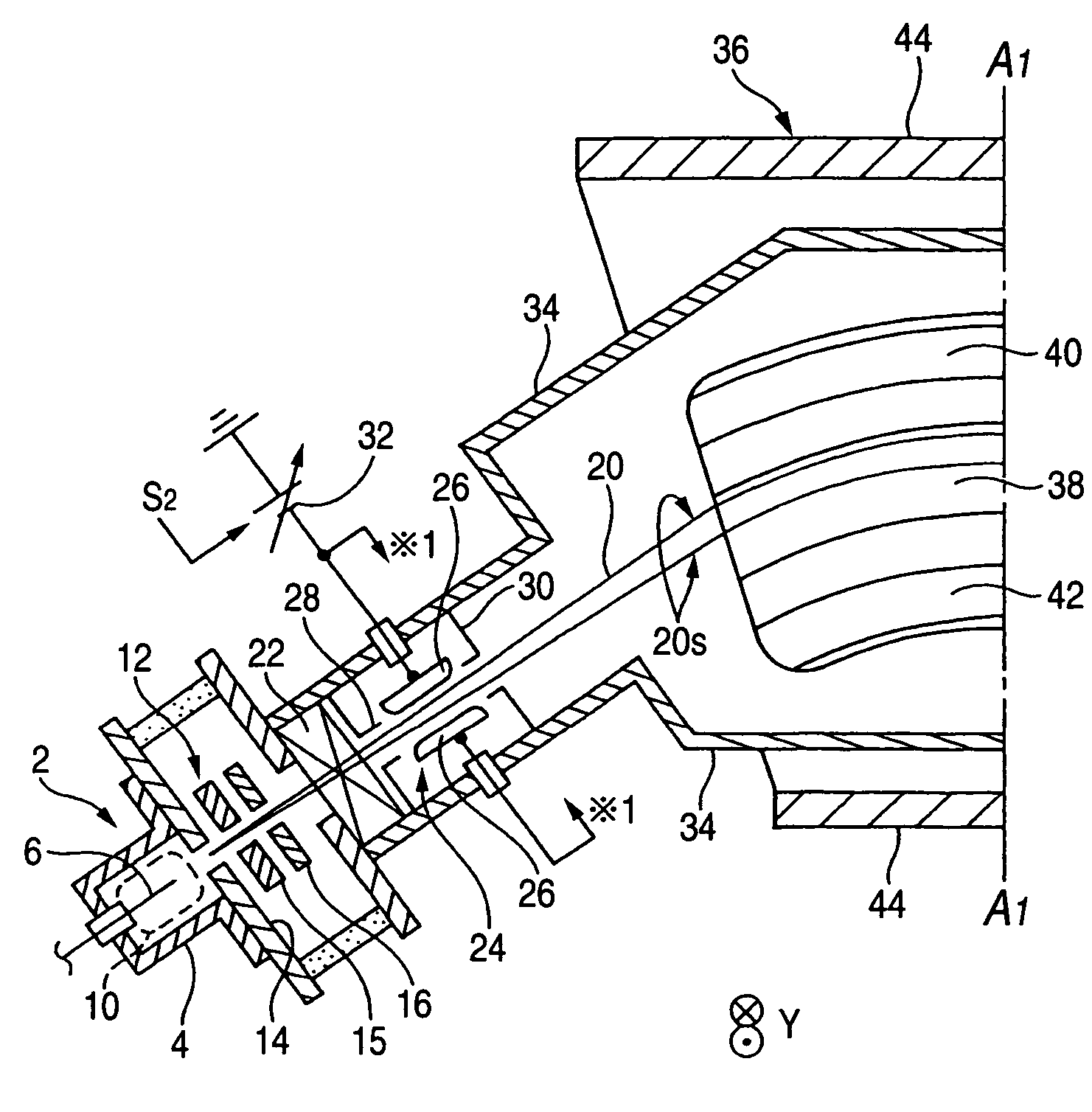
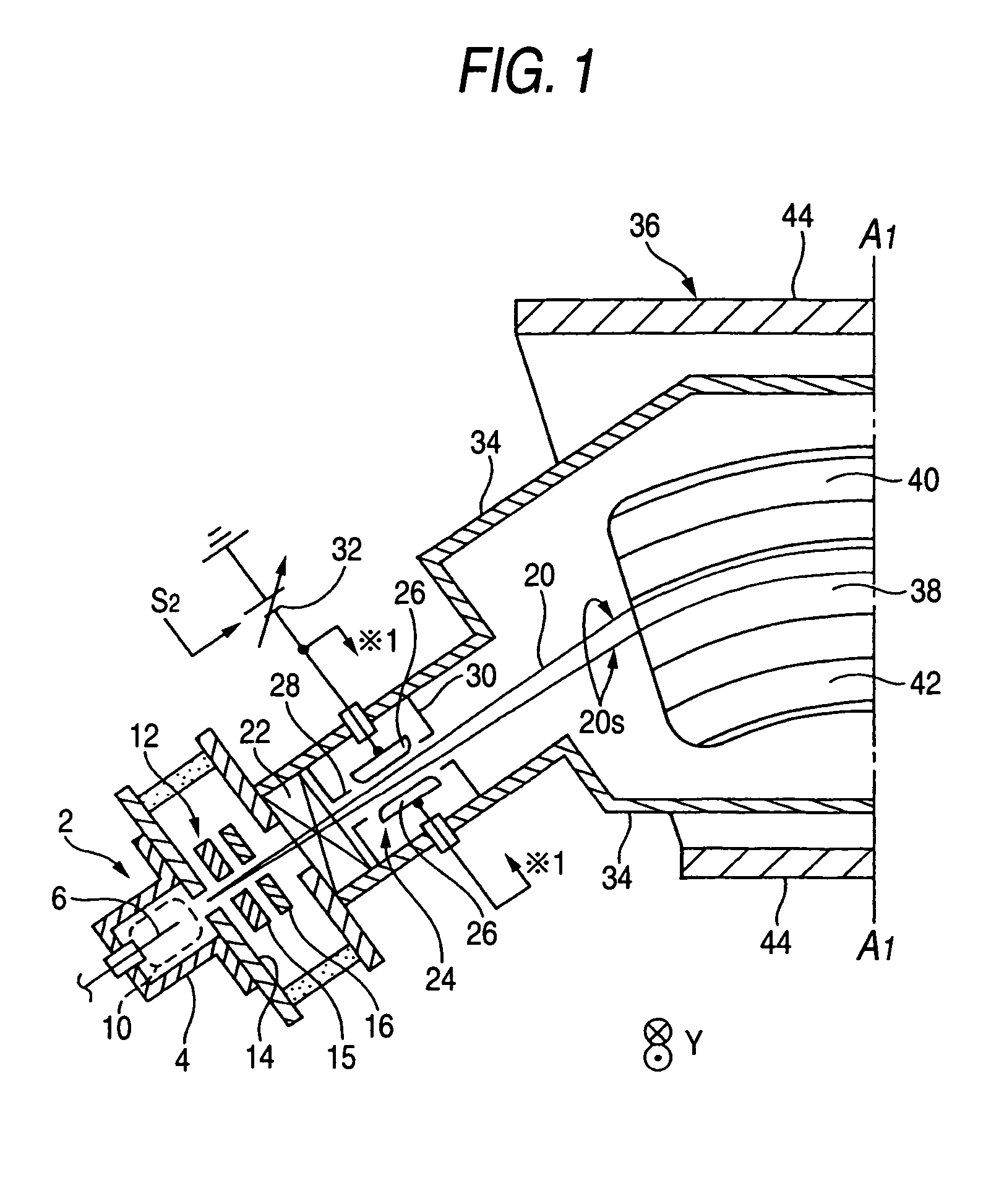
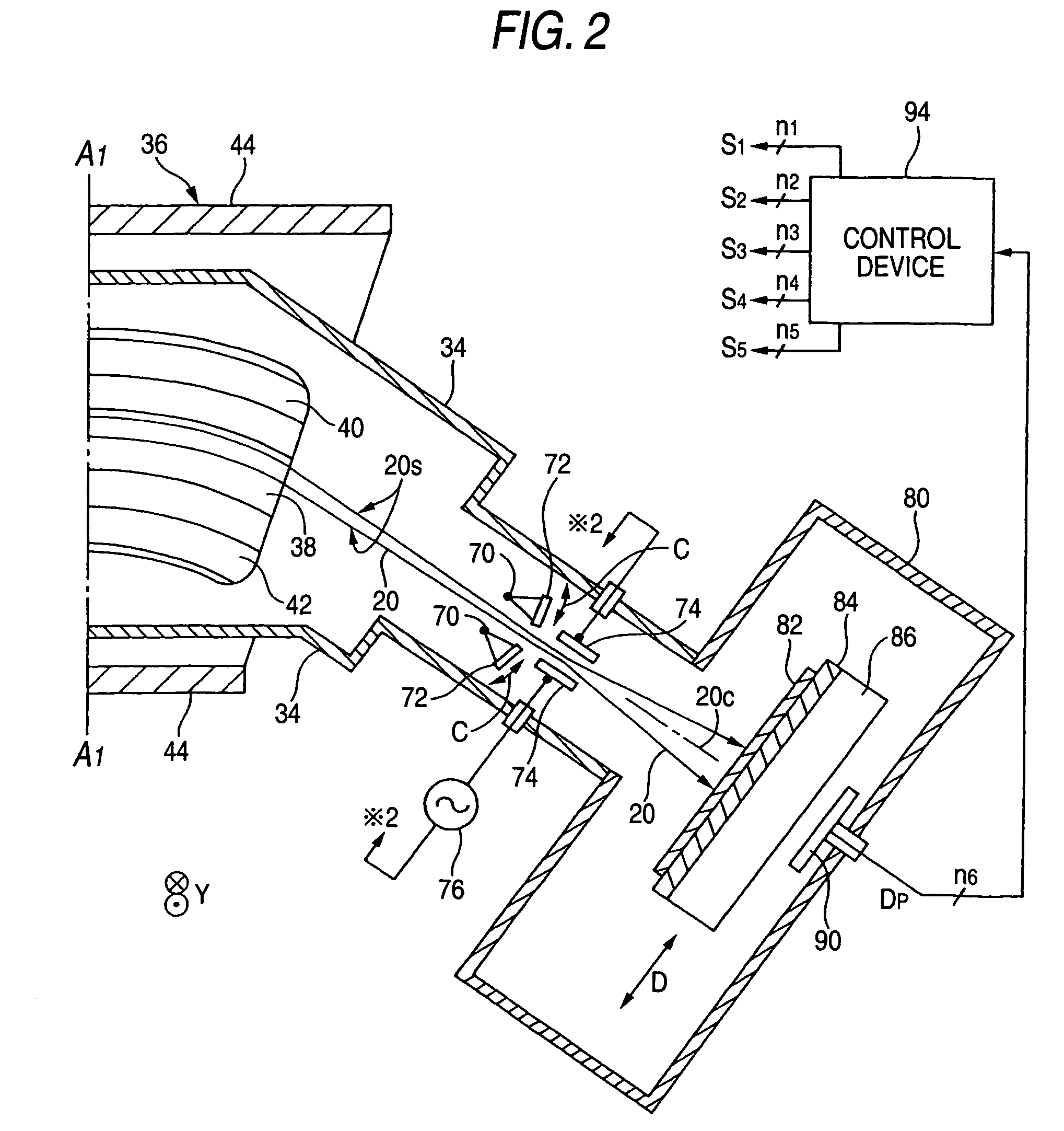
[0057]FIG. 1 is a transversal cross-sectional view showing a part of an embodiment of the ion implanting apparatus according to this invention and continuing to FIG. 2 at line A1—A1. FIG. 2 is a transversal cross-sectional view showing the remaining part of an embodiment of the ion implanting apparatus according to this invention and continuing to FIG. 1 at line A1—A1. FIG. 3 is a longitudinal cross-sectional view showing a part of an embodiment of the ion implanting apparatus according to this invention as shown in FIGS. 1 and 2 and continuing to FIG. 4 at line A2—A2. FIG. 4 is a longitudinal cross-sectional view showing the remaining part of an embodiment of the ion implanting apparatus according to this invention as shown in FIGS. 1 and 2 and continuing to FIG. 4 at line A2—A2.

[0058]This ion implanting apparatus, in principle, employs a square substrate 82 as shown in e.g. FIG. 6 as a processed body. The width of the narrow side 82a of the substrate 82 is referred to as a narrow ...


PUM

PropertyMeasurementUnit
widthaaaaaaaaaa
widthaaaaaaaaaa
angleaaaaaaaaaa

Abstract

The ion implanting apparatus according to this invention includes: an ion source for producing the ion beam 20 including desired ion species and being shaped in a sheet with a width longer than a narrow width of a substrate 82, a mass separating magnet 36 for selectively deriving the desired ion species by bending the ion beam in a direction perpendicular to a sheet face thereof, a separating slit 72 for selectively making the desired ion species pass through by cooperating with the mass separating magnet 36, and a substrate drive device 86 for reciprocatedly driving the substrate 82 in a direction substantially perpendicular to the sheet face 20s of the ion beam 20 within an irradiating area of the ion beam 20 which has passed through a separating slit 72.

Description

BACKGROUND OF THE INVENTION[0001]1. Technical Field[0002]This invention relates to an ion implanting apparatus for performing ion implantation by irradiating a substrate such as a semiconductor substrate, a substrate for a flat panel, etc. (in other words, workpiece or a processed body. The same goes for the following description). More particularly, this invention relates to an ion implanting apparatus which is appropriately adaptable to up-sizing of the substrate (in other words, large-scaling. The same goes for the following description). Incidentally, the ion implanting apparatus defined herein includes an apparatus called an ion doping apparatus.[0003]2. Background Art[0004]An example of ion implanting apparatus capable of irradiating a substrate with an ion beam having a large width and parallelized is disclosed in JP-A-2000-505234 (page 14, line 14 to page 15, line 15, FIG. 5). This ion implanting apparatus has a structure in which a unidirectionally diverging fan-shaped ion ...

Claims


Application Information

Patent Timeline
Patent Type & Authority Patents(United States)
IPC IPC(8): H01J37/00G01N21/00H01J37/317H01L21/265
CPCH01J37/3171H01J2237/0455H01J2237/057H01L21/26513H01J2237/20228H01J2237/24528H01J2237/24542H01J2237/1502H01L21/2658H01L21/265
Inventor MAENO, SYUICHINAITO, MASAOANDO, YASUNORIGLAVISH, HILTON F.
Owner NISSIN ION EQUIP CO LTD
Why Eureka
Try Eureka