Backlight driving apparatus

a driving apparatus and backlight technology, applied in the field of backlight, can solve the problems of complex circuit configuration and increase in cost, and achieve the effect of uniform current balance of light emitting diode arrays and simplified circuit configurations

Active Publication Date: 2008-06-12
LG DISPLAY CO LTD
View PDF3 Cites 19 Cited by
  • Summary
  • Abstract
  • Description
  • Claims
  • Application Information

AI Technical Summary

Benefits of technology

[0015]An object of the present invention is to provide a backlight driving apparatus which is capable of simplifying a circuit configuration for driving of a plurality of light emitting diode arrays and making the current balance of the light emitting diode arrays uniform.

Problems solved by technology

The above-mentioned general backlight driving apparatus is disadvantageous in that the plurality of power sources 201 to 20n and the plurality of controllers must be provided to drive the plurality of LED arrays 101 to 10n, respectively, resulting in a complexity in circuit configuration and an increase in cost.

Method used


Image

  • Backlight driving apparatus
  • Backlight driving apparatus
  • Backlight driving apparatus

Examples


first embodiment

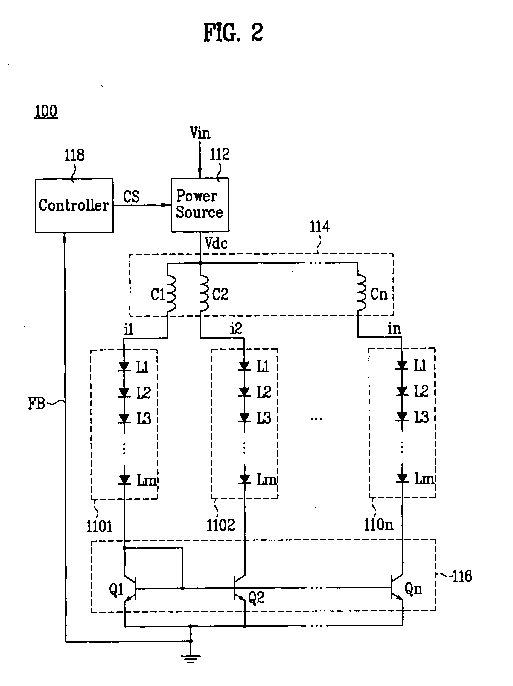
[0039]FIG. 2 is a schematic view of an embodiment of a backlight driving apparatus according to a

[0040]Referring to FIG. 2, the backlight driving apparatus 100 according to the first embodiment includes first to nth light emitting diode (LED) arrays 1101 to 110n each including a plurality of LEDs (L1 to Lm) connected in series, a power source 112 for generating a driving current Vdc, a current generator 114 for generating first to nth currents (i1 to in) to drive respectively the LED arrays 1101 to 110n using the driving current Vdc, a current mirror circuit 116 connected between the LED arrays 1101 to 110n and a ground voltage source for allowing the same amount of currents to flow respectively through the LED arrays 1101 to 10n, and a controller 118 for controlling the power source 112 based on a feedback signal outputted from the current mirror circuit 116.

[0041]The power source 112 generates the driving current Vdc using an input voltage Vin in response to a control signal CS fr...

second embodiment

[0061]FIG. 4 is a schematic view of an embodiment of a backlight driving apparatus according to a

[0062]Referring to FIG. 4, the backlight driving apparatus 200 according to the second embodiment includes first to nth LED arrays 2101 to 210n each including a plurality of LEDs (L1 to Lm) connected in series, a power source 212 for generating a driving current Vdc and supplying the generated driving current Vdc in common to the first to nth LED arrays 2101 to 210n, a current generator 214 for generating first to nth currents (i1 to in) using current flowing through the first LED array 2101, a current mirror circuit 216 for allowing the same amount of currents to flow respectively through the LED arrays 2101 to 210n based respectively on the first to nth currents (i1 to in), and a controller 218 for controlling the power source 212 based on a feedback signal outputted from the current mirror circuit 216.

[0063]The power source 212 generates the driving current Vdc using an input voltage ...

third embodiment

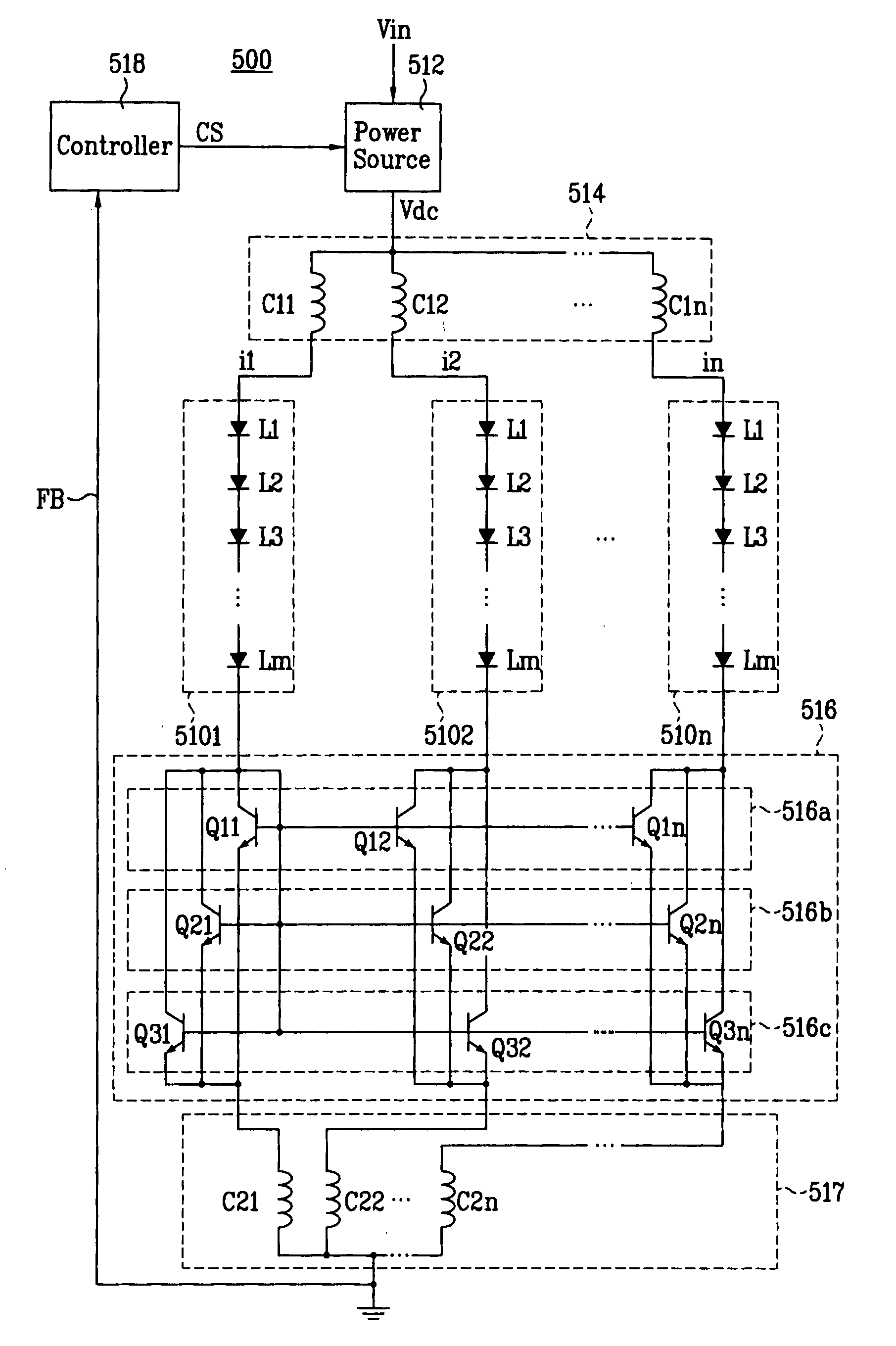
[0081]FIG. 8 is a schematic view of an embodiment of a backlight driving apparatus according to a

[0082]Referring to FIG. 8, the backlight driving apparatus 300 according to the third embodiment includes first to nth LED arrays 3101 to 310n each including a plurality of LEDs (L1 to Lm) connected in series, a power source 312 for generating a driving current Vdc and supplying the generated driving current Vdc in common to the first to nth LED arrays 3101 to 310n, a current mirror circuit 316 connected to the LED arrays 3101 to 310n for allowing the same amount of currents to flow respectively through the LED arrays 3101 to 310n, a current compensator 317 connected to the current mirror circuit 316 for compensating for a difference among the amounts of currents flowing respectively through the LED arrays 3101 to 310n, and a controller 318 for controlling the power source 312 based on a feedback signal outputted from the current compensator 317.

[0083]The power source 312 generates the d...


PUM


Abstract

A backlight driving apparatus is disclosed which is capable of simplifying a circuit configuration for driving of a plurality of light emitting diode arrays and making the current balance of the light emitting diode arrays uniform. The backlight driving apparatus includes n light emitting diode arrays that include a plurality of light emitting diodes connected in series, a power source for generating a driving current, a current generator for generating currents to drive the light emitting diode arrays using the driving current, respectively, and a current mirror circuit for allowing substantially the same amount of currents to flow respectively through the light emitting diode arrays based on current from any one of the n light emitting diode arrays.

Description

[0001]This application claims the benefit of Korean Patent Application No. 10-2006-0087849, filed on Sep. 12, 2006, which is hereby incorporated by reference as if fully set forth herein.BACKGROUND OF THE INVENTION[0002]1. Field of the Invention[0003]The present invention relates to a backlight, and more particularly, to a backlight driving apparatus which is capable of simplifying a circuit configuration for driving of a plurality of light emitting diode arrays and making the current balance of the light emitting diode arrays uniform.[0004]2. Discussion of the Related Art[0005]Generally, a liquid crystal display (LCD) device is comprised of an LCD panel which includes a plurality of liquid crystal cells arranged in a matrix configuration, and a plurality of control switches to switch video signals supplied to the respective liquid crystal cells; and a backlight unit to emit light to the LCD panel. The LCD device displays desired images on a screen by controlling the transmittance o...

Claims


Application Information

Patent Timeline
Patent Type & Authority Applications(United States)
IPC IPC(8): G09G3/36
CPCG09G3/3406G09G2320/0633G09G2320/0233G02F1/133G09G3/32
Inventor KIM, PU JINKIM, SEUNG HYUN
Owner LG DISPLAY CO LTD
Why Eureka
Try Eureka