Supercharge Your Innovation With Domain-Expert AI Agents!

Motor flange drill jig

A motor flange and drill die technology, which is applied to the drill die for workpieces and other directions, can solve the problems of inconvenient drill sleeve replacement, complicated operation steps, fixed drill sleeve size, etc., and achieves simple structure, cost reduction, and simple positioning. Effect

Inactive Publication Date: 2017-10-27
XIANGYANG QIJINGTE MECHANICAL & ELECTRICAL MFG CO LTD
View PDF0 Cites 8 Cited by
  • Summary
  • Abstract
  • Description
  • Claims
  • Application Information

AI Technical Summary

Problems solved by technology

The prior art motor flange drilling mold has the following defects: one is that the clamping device of the drilling mold adopts a general fixture for clamping and processing, the parts are more complicated, the clamping is not easy, the operation is cumbersome, and the cost is high; the other is that the motor flange of the prior art The drill sleeve and the mold hole of the drilling mold are connected by welding, which is difficult to disassemble, and it is inconvenient to replace the drill sleeve after it is damaged; the third is that the size of the drill sleeve is fixed, and it can only be applied to a specific size of the motor flange drilling process, which is universal Not strong; Fourth, the existing flange drilling jig positioning device uses positioning keys, positioning nuts or positioning pins, which not only need to drill holes on the drilling jig, but also need to punch holes on the motor flange to match the positioning, and the operation steps are cumbersome

Method used


Image

  • Motor flange drill jig
  • Motor flange drill jig

Examples


Embodiment Construction

[0018] The present invention will be further described below in conjunction with the accompanying drawings and specific embodiments.

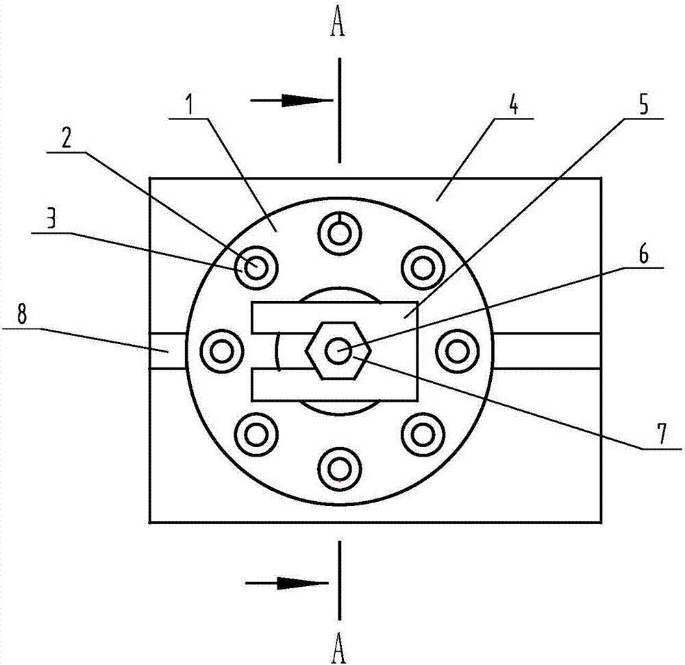
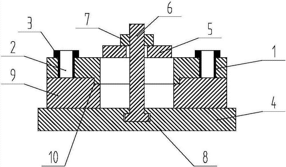
[0019] Such as figure 1 , figure 2 Shown, a kind of motor flange drilling template comprises drilling template 1, locating device and clamping device, and drilling template 1 is circular-shaped, and on the drilling template 1, more than one mold hole 2 is evenly arranged along the same circumference, and mold hole 2 A drill sleeve 3 is sleeved inside, and the clamping device includes a base 4, a U-shaped pressure plate 5, a locking bolt 6 and a locking nut 7. The base 4 is provided with an inverted T-shaped groove 8, and the head of the locking bolt 6 is clamped. In the inverted T-shaped slot 8, and can slide in the inverted T-shaped slot 8, the screw rod of the locking bolt 6 passes through the inner ring of the motor flange 9 placed on the base 4 and the inner ring of the drilling template 1 in sequence from bottom to top With the U-shaped...


PUM


Abstract

A motor flange drilling mold, comprising a drilling template (1), a positioning device and a clamping device, the drilling template (1) is circular, and more than one mold hole (2) is uniformly arranged on the same circumference on the drilling template (1). ), the mold hole (2) is sleeved with a drill sleeve (3), the clamping device includes a base (4), a U-shaped pressure plate (5), a locking bolt (6) and a locking nut (7), the base (4 ) is provided with an inverted T-shaped slot (8), the head of the locking bolt (6) is clamped in the inverted T-shaped slot (8), and can slide in the inverted T-shaped slot (8), and the locking bolt ( 6) The screw rod passes through the inner ring of the motor flange (9) placed on the base (4), the inner ring of the drill template (1) and the U-shaped groove of the U-shaped pressure plate (5) from bottom to top, and the lock nut ( 7) After screwing in and pressing the U-shaped pressure plate (5), clamp the drilling template (1) and the motor flange (9). The motor flange drilling mold of the invention has the advantages of simple structure, convenient operation, low cost and strong practicability.

Description

technical field [0001] The invention relates to a flange drilling mold, in particular to a motor flange drilling mold, and belongs to the technical field of machinery. Background technique [0002] Motor flange drilling jig is a kind of jig for auxiliary motor flange drilling. Its function is to ensure the position accuracy of motor flange drilling and improve drilling efficiency. The structure of the motor flange drilling template generally includes the drilling template, flange positioning and clamping device. The prior art motor flange drilling mold has the following defects: one is that the clamping device of the drilling mold adopts a general fixture for clamping and processing, the parts are more complicated, the clamping is not easy, the operation is cumbersome, and the cost is high; the other is that the motor flange of the prior art The drill sleeve and the mold hole of the drilling mold are connected by welding, which is difficult to disassemble, and it is inconve...

Claims


Application Information

Patent Timeline
Patent Type & Authority Applications(China)
IPC IPC(8): B23B47/28
CPCB23B47/28
Inventor 李元杰孟勇付
Owner XIANGYANG QIJINGTE MECHANICAL & ELECTRICAL MFG CO LTD
Features
  • R&D
  • Intellectual Property
  • Life Sciences
  • Materials
  • Tech Scout
  • Unparalleled Data Quality
  • Higher Quality Content
  • 60% Fewer Hallucinations
Learn More