Engine crankshaft storage rack

A technology for engines and storage racks, which is applied in the direction of tool storage devices, manufacturing tools, etc., can solve the problems of not being able to meet the storage requirements of engine crankshafts of different models, a wide variety of storage racks, and low use efficiency, and achieve high reliability, convenient operation, and The effect of increasing usage

Pending Publication Date: 2017-10-27
CRRC LUOYANG CO LTD
View PDF6 Cites 5 Cited by
  • Summary
  • Abstract
  • Description
  • Claims
  • Application Information

AI Technical Summary

Problems solved by technology

[0002] At present, with the development of the railway locomotive and rolling stock manufacturing industry, there are more and more specifications and models of internal combustion locomotives. The locomotive engine needs to be disassembled during overhaul. The crankshaft is an important part of the engine. The crankshaft needs to be equipped with a special storage rack when disassembling. , in order to facilitate transportation and avoid bumping during transportation, the existing crankshaft storage racks cannot meet the storage requirements of different types of engine crankshafts, resulting in a wide variety of storage racks, which are extremely inconvenient and inefficient to use

Method used


Image

  • Engine crankshaft storage rack
  • Engine crankshaft storage rack
  • Engine crankshaft storage rack

Examples


Embodiment Construction

[0019] The specific implementation manners of the present invention will be described in detail below in conjunction with the accompanying drawings.

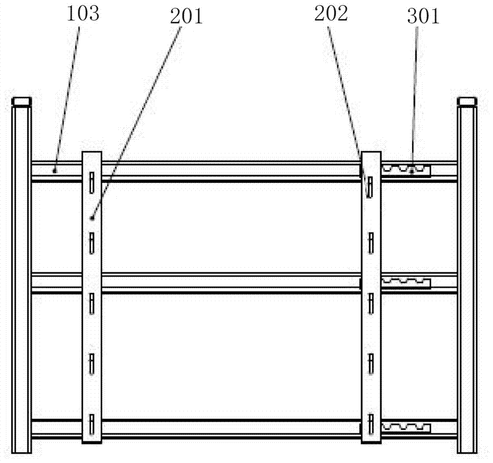
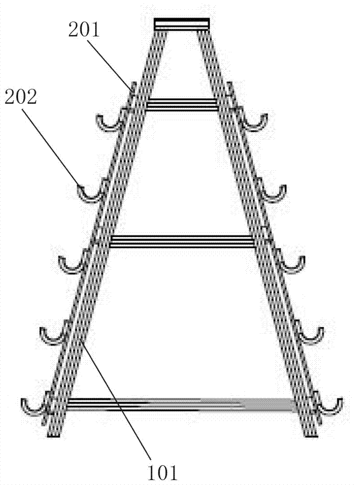
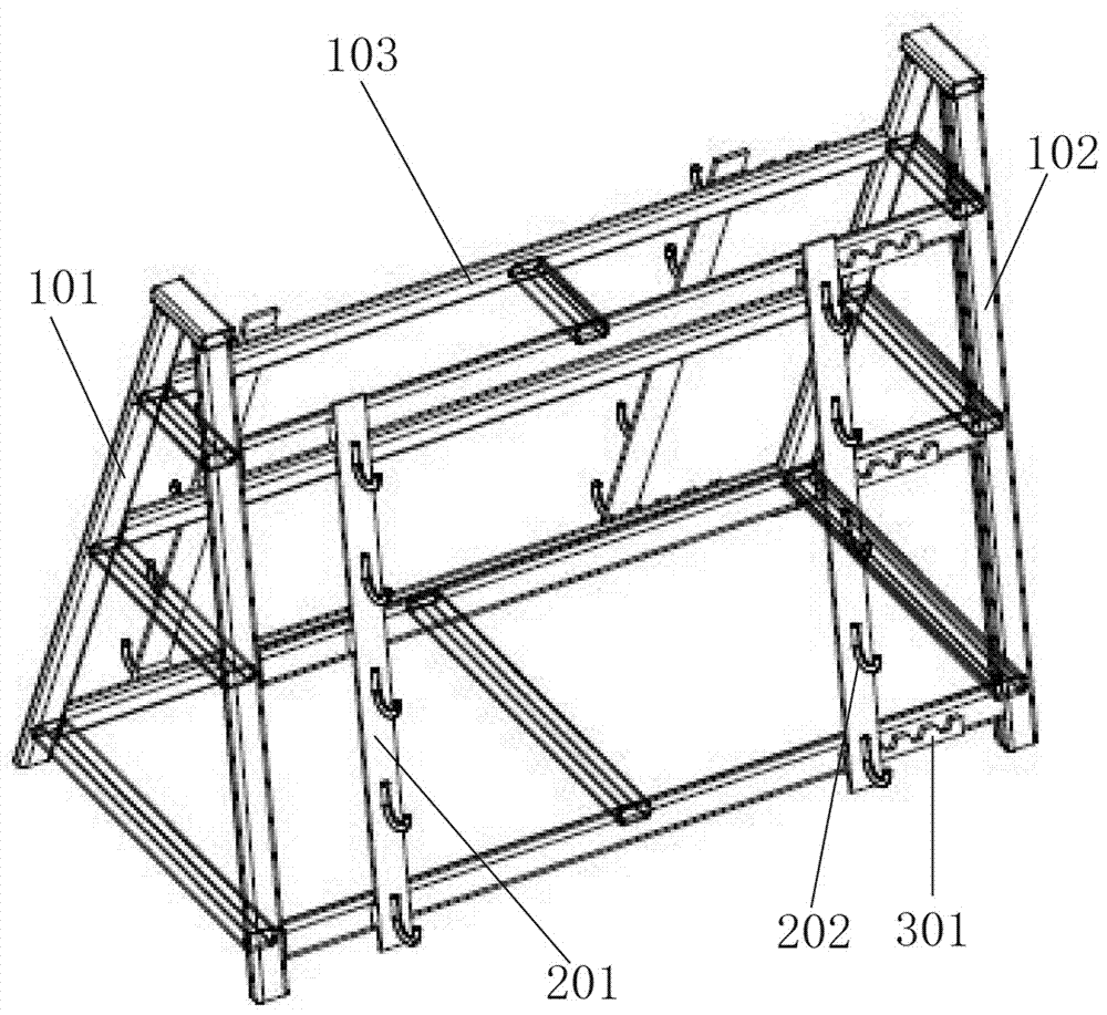
[0020] see Figure 1-Figure 5 , an engine crankshaft storage rack according to the present invention, comprising a left bracket 101 and a right bracket 102, the left bracket 101 and the right bracket 102 are both in a herringbone structure, and the two are arranged correspondingly on the left and right; between the left bracket and the right bracket A plurality of cross braces 103 are arranged at intervals, and the cross braces 103, the left bracket 101 and the right bracket 102 form a support frame; two support brackets 201 are correspondingly arranged on each side of the support frame, and the two supports The bracket 201 is provided with multiple groups of corresponding hooks 202, and the engine crankshaft is matched and placed on the two corresponding hooks 202; at least one of the two support brackets 201 is provided with a...


PUM


Abstract

The invention belongs to the technical field of locomotive manufacture, and particularly relates to an engine crankshaft storage rack which comprises a left reversed V-shaped support, a right reversed V-shaped support, a plurality of lateral braces and two supporting brackets, wherein the lateral braces are connected between the left support and the right support at intervals. The lateral braces, the left support and the right support form a supporting frame, multi-group corresponding hooks are arranged on the two supporting brackets, an engine crank is placed on two corresponding hooks in a matched manner, an adjusting component is arranged between at least one of the two supporting brackets and the supporting frame, the corresponding supporting brackets are supported on the supporting frame through the adjusting component, and the distance between the two supporting brackets can be adjusted through the adjusting component. The universal engine crankshaft storage rack meets storage requirements of crankshafts of different lengths and is convenient to operate, practical, safe and high in reliability.

Description

technical field [0001] The invention belongs to the technical field of railway locomotive and vehicle manufacturing, and in particular relates to an engine crankshaft storage rack. Background technique [0002] At present, with the development of the railway locomotive and rolling stock manufacturing industry, there are more and more specifications and models of internal combustion locomotives. The locomotive engine needs to be disassembled during overhaul. The crankshaft is an important part of the engine. The crankshaft needs to be equipped with a special storage rack when disassembling. , in order to facilitate transportation and avoid bumping during transportation, the existing crankshaft storage racks cannot meet the storage requirements of different types of engine crankshafts, resulting in a wide variety of storage racks, which are extremely inconvenient and inefficient to use. Contents of the invention [0003] The object of the present invention is to address the ...

Claims


Application Information

Patent Timeline
Patent Type & Authority Applications(China)
IPC IPC(8): B25H3/04
CPCB25H3/04
Inventor 唐磊苏永军王勇涛
Owner CRRC LUOYANG CO LTD
Why Eureka
Try Eureka