Cutting die with automatic waste clearing function

An automatic cleaning and functional technology, which is applied in metal processing and other fields, can solve the problems of negative impact of waste process, inability to clean dust and waste, etc.

Active Publication Date: 2017-10-27
CHANGSHU MUTUAL TEK CO LTD
View PDF4 Cites 1 Cited by
  • Summary
  • Abstract
  • Description
  • Claims
  • Application Information

AI Technical Summary

Problems solved by technology

[0002] During the die-cutting process of various circuit boards, a large amount of fine wastes are often produced, and these fine wastes also have a certain degree of viscosity. Different degrees of negative impact on subsequent processes

Method used


Image

  • Cutting die with automatic waste clearing function
  • Cutting die with automatic waste clearing function
  • Cutting die with automatic waste clearing function

Examples


Embodiment 1

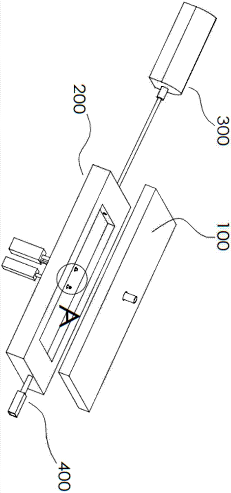
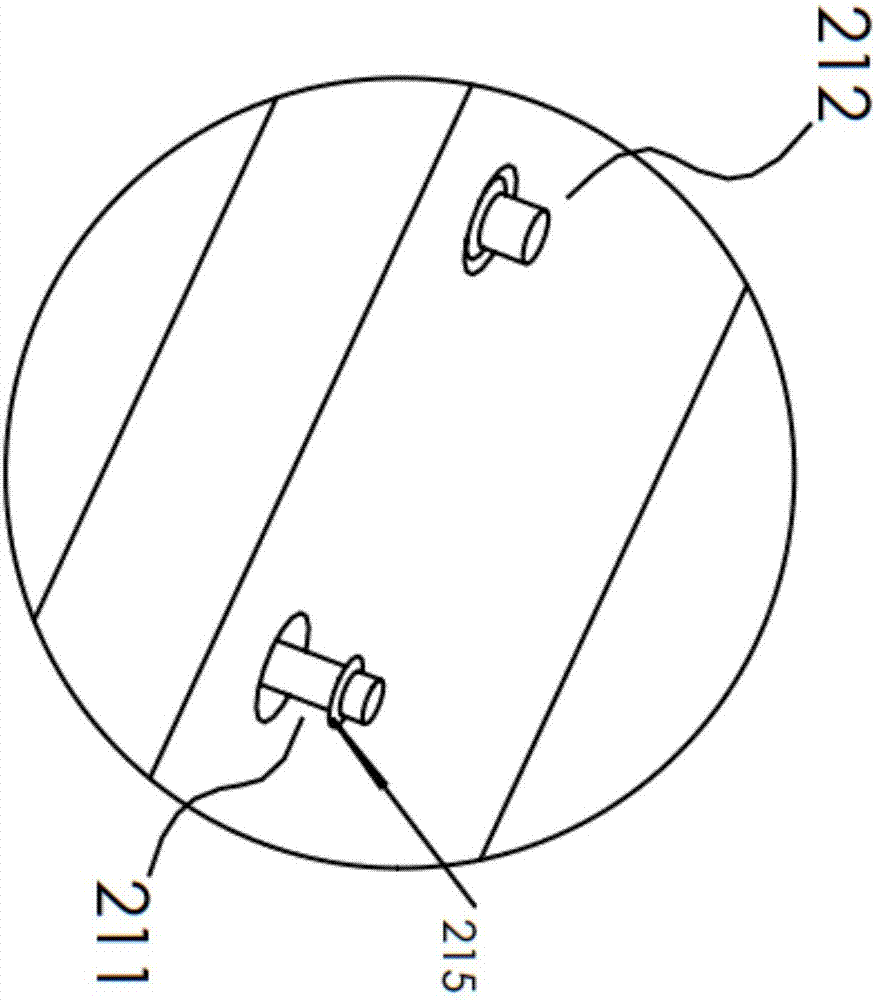
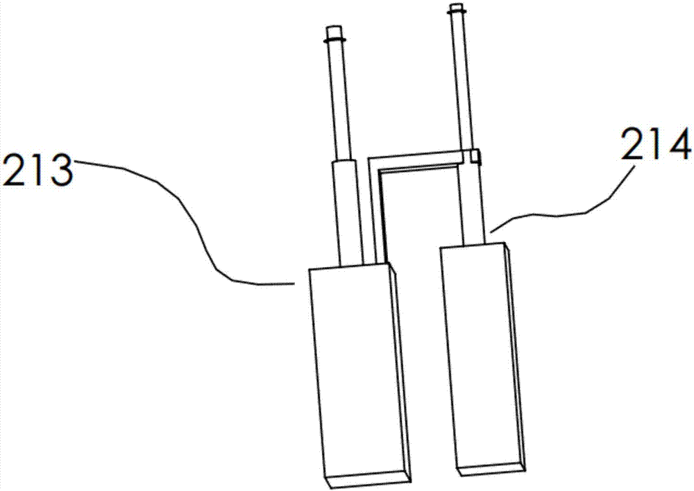
[0033] A cutting die with automatic waste removal function, comprising: a male template 100, whose main body is a flat cuboid structure; a female template 200, whose main body is a flat cuboid structure, and the female template 200 is located below the male template 100, and The upper surface of the 200 is provided with a recessed cavity 210 for placing the workpiece to be processed. The recessed cavity 210 is provided with a first through hole and at least a second through hole, and a first through hole is provided in the first through hole. Locating pin 211, second locating pin 212 is arranged in the second through hole, the lower side of the first locating pin 211 is connected with the telescopic rod of the first cylinder 213, the lower side of the second locating pin 212 is connected with the second The telescopic rod connection of the cylinder 214; the gas device 300, which includes a horizontally arranged first air valve 310 and at least one vertically arranged second air...

Embodiment 2

[0038] The suction cavity 410 is disposed on a second side of the master template 200 , and the second side is opposite to the first side. The suction cavity 410 is provided with a trumpet-shaped suction port, and the suction port faces the concave cavity 210 . The first end of the waste storage box 420 communicates with the suction cavity 410 , and the second end of the waste storage box 420 is open. Preferably, the waste material storage box 420 is provided with a filter structure, and the diameter of the holes on the filter structure is less than 0.1 mm.

[0039] By arranging the suction chamber 410 opposite to the first air valve 310 , an air fluid channel is formed, so that all waste materials can be collected into the waste material storage box 420 .

[0040] As mentioned above, the workpiece to be processed is lifted through the edge structure to provide a stable support, and at the same time the edge structure is bent downward so that waste materials will not accumula...


PUM

PropertyMeasurementUnit
Diameteraaaaaaaaaa

Abstract

The invention relates to a cutting die with an automatic waste clearing function. The cutting die comprises a male die plate, a female die plate, a gas device and a waste discharge device. The female die plate is positioned below the male die plate, the upper surface of the female die plate is provided with a concave cavity for placement of a to-be-machined workpiece, the concave cavity is provided with a first through hole and at least one second through hole, a first positioning pin is arranged in the first through hole, a second positioning pin is arranged in each second through hole, the lower side of the first positioning pin is connected with a telescopic rod of a first air cylinder, and the lower side of each second positioning pin is connected with a telescopic rod of a second air cylinder. The gas device comprises a first gas valve in horizontal arrangement and at least one second gas valve in vertical arrangement, the first gas valve is fixed to a first side of the female die plate, and gas outlets of the first gas valve and each second gas valve face the concave cavity. The waste discharge device comprises a suction cavity and a waste collection box, and the waste collection box is communicated with the suction cavity. The cutting die has the advantage that small-particle wastes can be cleared thoroughly.

Description

technical field [0001] The invention relates to the field of die-cutting, in particular to a cutting die with automatic waste removal function. Background technique [0002] During the die-cutting process of various circuit boards, a large amount of fine wastes are often produced, and these fine wastes also have a certain degree of viscosity. cause varying degrees of negative impact on subsequent processes. Contents of the invention [0003] An object of the present invention is to solve at least the above-mentioned problems or disadvantages and to provide at least the advantages that will be described hereinafter. [0004] Another object of the present invention is to provide a cutting die with automatic waste removal function, through which the edge structure jacks up the workpiece to provide a stable support, and at the same time the edge structure bends downward so that waste will not accumulate on the edge Above the structure; through the first positioning pin and t...

Claims


Application Information

Patent Timeline
IPC IPC(8): B26F1/44B26D7/18
CPCB26D7/1863B26F1/44
Inventor 张智明邱士于李素贞
Owner CHANGSHU MUTUAL TEK CO LTD
Why Eureka
Try Eureka