Sharp-vertex dual-sweepback osculating-cone wave rider with transition sections

A waverider and transition section technology, applied in the field of apex double swept close-cone waverider, can solve the problems of reducing aerodynamic performance, large resistance, lift loss, etc., and achieve the effect of improving aerodynamic performance and favorable design

Active Publication Date: 2017-10-27
CALCULATION AERODYNAMICS INST CHINA AERODYNAMICS RES & DEV CENT
View PDF4 Cites 1 Cited by
  • Summary
  • Abstract
  • Description
  • Claims
  • Application Information

AI Technical Summary

Problems solved by technology

In this flow field, the lower surface flow is limited by the attached shock wave without leakage to the upper surface, whereas for conventional layouts, this upper and lower surface leakage can result in up to 25% lift loss
Although the generation and design methods of waveriders have been deeply studied, there are still the following problems: 1. The volumetric efficiency and lift-to-drag ratio are contradictory, which must be weighed during design; Aerodynamic performance but lower volume efficiency. Designing a compression surface can improve volume efficiency but reduce aerodynamic performance. At present, it is generally designed as a free flow surface, which does not contribute to aerodynamic performance and volume efficiency; 3. Non-design state, especially low-speed performance is poor , because the waverider can only ride waves in the design state
However, due to the small plane area of ​​this shape, the lift increase it brings is limited, and the low-speed performance is not good, the resistance is large, and the take-off and landing performance is very poor.

Method used


Image

  • Sharp-vertex dual-sweepback osculating-cone wave rider with transition sections
  • Sharp-vertex dual-sweepback osculating-cone wave rider with transition sections
  • Sharp-vertex dual-sweepback osculating-cone wave rider with transition sections

Examples


Embodiment Construction

[0044] The present invention implements according to the following steps:

[0045] 1. According to the design requirements, the cruising Mach number and flight altitude are given;

[0046] 2. Determine the first sweep angle, determine the upper limit of the waverider sweep angle according to the cruising Mach number, and then select a reasonable sweep angle according to the design requirements;

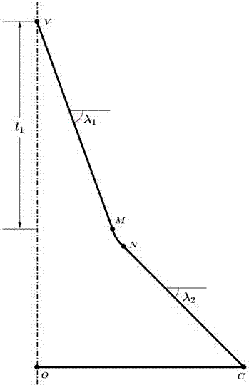
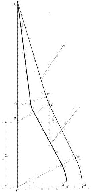
[0047] 3. Determine the second sweep angle, the value of which is between the first sweep angle and zero;

[0048] 4. To determine the shock angle, first determine the range of the shock angle by the cruise Mach number and the first sweep angle, and then select a reasonable shock angle according to the design requirements;

[0049] 5. Determine the fuselage width corresponding to the first sweep angle, and determine the fuselage width corresponding to the first sweep angle according to the fuselage length and the first sweep angle;

[0050] Six, specify two control parameters of the t...


PUM


Abstract

The invention discloses a sharp-vertex dual-sweepback osculating-cone wave rider with transition sections. Each front edge of the wave rider consists of two straight sections and a transition curve for connecting the two corresponding straight sections; from a sharp vertex, each first straight section corresponds to a first sweepback angle, and each second straight section corresponds to a second sweepback angle; the angle of the two sweepback angles are controllable in a designing stage; and each transition curve is used for connecting the two corresponding straight sections, and enabling a first-order derivative and a second-order derivative to be continuous. Through the adoption of the wave rider disclosed by the invention, the sweepback effect of the wave rider can be effectively utilized to generate a stable separation vortex similar to a double-delta wing on the upper surface of the wave rider, and the plane area of the wave rider is enlarged by dual-sweepback front edges, so that the lifting force of the wave rider can be increased to a large extent, and the volumetric efficiency does not need to be reduced; the angle of the second sweepback angle is small, and the effect of the second sweepback angle is similar to the effect of the double-delta wing, so that improvement of the low-speed performance of the wave rider is facilitated; and the situation that the front edges of two sweepback parts are in first-order derivative continuity in geometry is guaranteed by the transition sections.

Description

technical field [0001] The invention relates to the field of aerodynamics, in particular to a pointed double-sweep close cone waverider with a transition section. Background technique [0002] When an aircraft with a traditional layout flies at hypersonic speed, the maximum lift-to-drag ratio has the following relationship with the flight Mach number: [0003] [0004] where M ∞ is the flight Mach number. It can be seen from the above formula that when the traditional layout is at a high Mach number, the maximum lift-to-drag ratio can only reach about 4, that is, there is a "lift-to-drag ratio barrier". The waverider can break the "lift-to-drag ratio barrier" of the traditional layout. The relationship between the maximum lift-to-drag ratio of the aircraft with the waverider layout and the flight Mach number is: [0005] [0006] The above formula shows that when the waverider layout is at a high Mach number, the maximum lift-to-drag ratio can reach about 6. The re...

Claims


Application Information

Patent Timeline
Patent Type & Authority Applications(China)
IPC IPC(8): B64C1/00
CPCB64C1/0009B64C2001/0045
Inventor 段焰辉吴文华范召林张培红刘深深余雷童富林赵鹏
Owner CALCULATION AERODYNAMICS INST CHINA AERODYNAMICS RES & DEV CENT
Why Eureka
Try Eureka