Bridge frame walking driving mechanism of bridge crane

An overhead crane, traveling drive technology, applied in the directions of traveling mechanism, load hanging element, transportation and packaging, can solve the problems of increasing machine cost, reducing wheel life, uneven force on wheels, etc., to protect wheels and rails. , the inertia walking distance is short, the effect of shortening the transmission distance

Inactive Publication Date: 2017-10-27
ANHU WUHU CHANGJIANG JACK UP EQUIP CO LTD
View PDF7 Cites 1 Cited by
  • Summary
  • Abstract
  • Description
  • Claims
  • Application Information

AI Technical Summary

Problems solved by technology

[0004] (1) Most of the trolley driving mechanisms of the existing bridge cranes control the wheels on both sides through the motors and reducers located on both sides of the main girder, which not only increases the cost of the machine, but also requires two motors and reducers The model, speed, and performance are all the same, and the driving devices on both sides must rotate synchronously at the same time. Such a driving device is likely to change speed due to a failure of a certain motor or reducer, which will cause uneven force on the wheels on both sides and cause rail gnawing. , There is no direct connection between the two wheels, and the two wheels are also easy to deviate outward or inward, resulting in rail gnawing phenomenon. The rail gnawing phenomenon is that the edge of the wheel rubs against the edge of the track, which will cause great wear and tear on the wheel and track, and reduce the life of the wheel. ;
[0005] (2) The motor shaft is connected to the input shaft of the reducer through the transmission shaft, and then transmitted. The transmission of the rotational force of the motor shaft through the transmission shaft will cause loss, so the transmission efficiency of the motor to the reducer will be reduced, and a motor in the crane cart and In order to facilitate disassembly and maintenance, the design of a reducer generally installs the motor and the reducer on the left or right side of the main beam near the end face. This installation method makes the motor less sensitive to the torque of the reducer due to the increased torque. The output efficiency of the wheels is greatly reduced. At the same time, because the physical center of gravity of the main girder is shifted due to the gravity installed inside, the trolley is generally located in the middle when the crane is unloaded, so the forces on the left and right wheels of the cart are unbalanced at this time, and the cart runs Unstable and prone to rail gnawing;
[0006] (3) Most of the reducers of the trolley driving mechanism of the existing bridge cranes use gear reducers, not to mention the noise, and the deceleration efficiency is relatively low, and the structure of multiple transmission wheels must be used to achieve high performance. The deceleration efficiency increases the complexity of the reducer structure, and the existing brakes are generally installed on the motor. After the motor brakes, the reducer and the wheels will automatically walk a certain distance due to inertia, and the inertial travel distance of the cart is longer. Long, which prolongs the unloading time of the goods and reduces the work efficiency of the lifting project

Method used


Image

  • Bridge frame walking driving mechanism of bridge crane
  • Bridge frame walking driving mechanism of bridge crane
  • Bridge frame walking driving mechanism of bridge crane

Examples


Embodiment

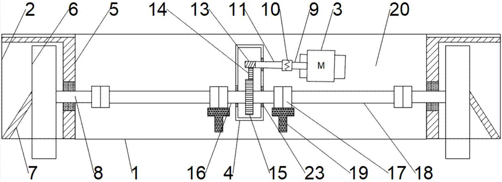
[0027] Such as figure 1 As shown, the present invention provides a traveling driving mechanism for a bridge crane. Connected with the main beam 1, the end beam 2 is equipped with wheels 6 through the angular bearing box 5, and the angular bearing box 5 is installed on the outside of the end beam 2, and the angular bearing box 5 serves to fix the wheels and bear the pressure of the cart , so that the heavy-duty running of the cart is smoother, the angular bearing box 5 includes the angular box 7 and the wheel axle 8, the angular box 7 and the wheel 6 are installed on the outside of the wheel axle 8, the angular box 7 can be well The wheel 6 is limited, and the corner box 7 is provided with several bearing groups for buffering the gravity of the wheel shaft 8.

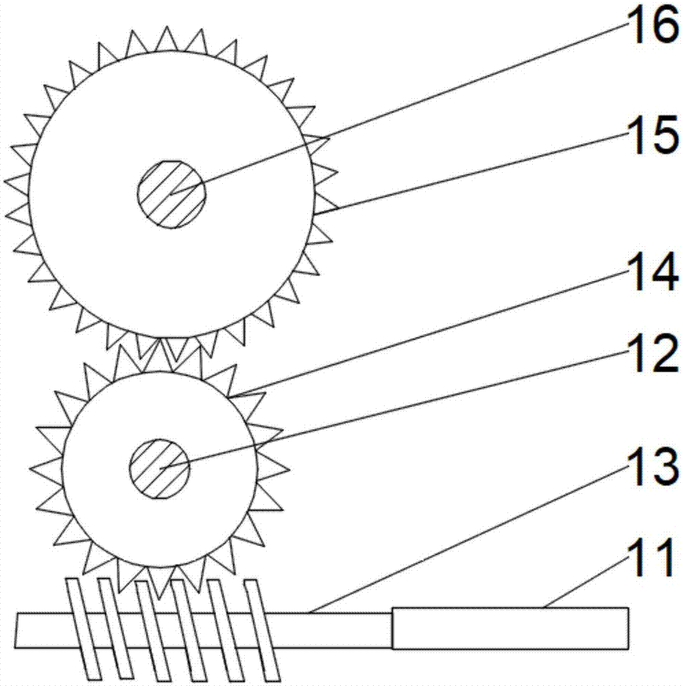
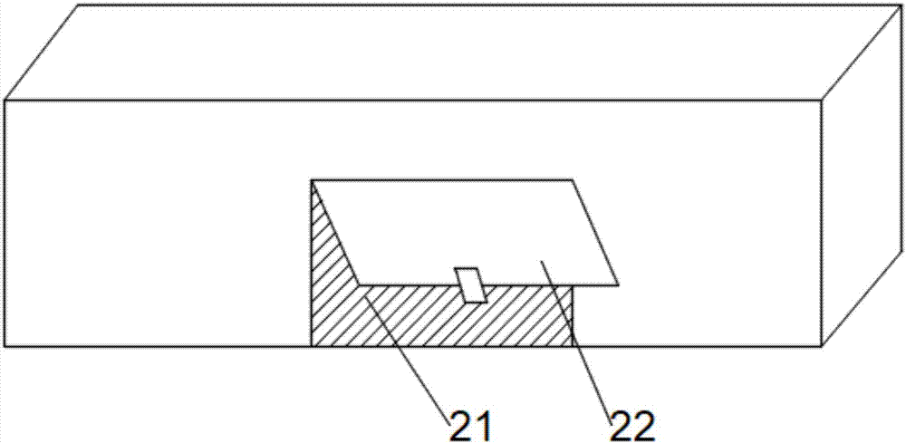
[0028] Such as figure 1 with image 3 As shown, a motor 3 and a reducer 4 are installed in the center of the main beam 1, the main beam 1 has an internal hollow structure, a hollow interlayer 20 is installed in the ho...


PUM


Abstract

The invention discloses a cart traveling drive mechanism of an overhead crane, which comprises a main beam, end beams are fixedly installed at both ends of the main beam, a motor and a reducer are installed in the inner center of the main beam, and the end beams are installed through an angle bearing box. The wheel, the angle bearing box includes the wheel shaft, one end of the motor extends out of the motor shaft, the motor shaft is connected with the input shaft through the plum blossom coupling, one end of the input shaft is connected with the worm, the worm is connected with the transmission wheel and the output wheel in turn, and the center of the output wheel is fixed. An output shaft is installed, the two ends of the output shaft are connected with a reduction rod, and a brake is installed on the top of the coupling. A motor and a reducer are used to control the rotation of the wheels on the left and right sides of the main beam at the same time to protect the wheels and rails. The design makes the transmission efficiency of the motor to the reducer higher, and the deceleration efficiency is higher through the worm gear-worm reducer. The self-locking structure of the reducer cooperates with the brake to brake faster and more timely, improving the working efficiency of the crane.

Description

technical field [0001] The invention relates to the technical field of cranes, in particular to a traveling driving mechanism of a bridge crane. Background technique [0002] The bridge crane is a kind of bridge type crane whose bridge frame runs on the elevated track, also known as the crane. The bridge frame of the bridge crane runs longitudinally along the rails laid on the elevated sides on both sides, and the lifting trolley runs horizontally along the rails laid on the bridge frame, forming a rectangular working range, which can make full use of the space under the bridge frame for hoisting and transporting materials. Hindered by ground equipment. This kind of crane is widely used in indoor and outdoor warehouses, workshops, docks and open-air storage yards. The single girder bridge consists of a single main girder and end girders located on both sides of the span, and the double girder bridge consists of two main girders and end girders. The main girder is rigidly ...

Claims


Application Information

Patent Timeline
Patent Type & Authority Applications(China)
IPC IPC(8): B66C9/14B66C9/10
CPCB66C9/14B66C9/10
Inventor 苗则波
Owner ANHU WUHU CHANGJIANG JACK UP EQUIP CO LTD
Why Eureka
Try Eureka