Method for measuring dynamic liquid surface of oil well with frequency difference infrasonic wave generator

A technology of infrasonic wave and generator, which is applied in the field of oil and gas field development, can solve the problems of signal strength depletion, uncontrollable infrasonic wave, discontinuity, etc., and achieve the effect of low operation cost and construction intensity, more precise reflection wave position, and definite reflection wave position

Active Publication Date: 2017-10-27
XI'AN PETROLEUM UNIVERSITY
View PDF11 Cites 8 Cited by
  • Summary
  • Abstract
  • Description
  • Claims
  • Application Information

AI Technical Summary

Problems solved by technology

At present, the methods of measuring the dynamic liquid level include pressure sensor testing, emptying shells, and pneumatic sound source testing. Due to the problems of complicated operation, relatively poor safety and reliability in pressure sensor testing and emptying shells, pneumatic sound sources are rarely used. It is the most widely used measurement method at present. Using the principle of sound waves, it is mainly divided into two types: sound wave type and infrasonic type. Although it has the characteristics of stable signal strength, low attenuation, and long-distance transmission, the application of infrasonic wave generators is limited due to various problems. For example,

Method used


Image

  • Method for measuring dynamic liquid surface of oil well with frequency difference infrasonic wave generator
  • Method for measuring dynamic liquid surface of oil well with frequency difference infrasonic wave generator
  • Method for measuring dynamic liquid surface of oil well with frequency difference infrasonic wave generator

Examples


Embodiment Construction

[0026] The operating method of the present invention will be discussed in detail below in conjunction with the accompanying drawings.

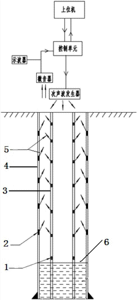
[0027] Such as figure 1 As shown, a method for measuring the dynamic liquid level of an oil well with a frequency difference type infrasonic generator comprises the following steps:

[0028] (1) Pre-installed echo

[0029] During casing and tubing operations in oil wells, a casing echo 2 is installed on the inside of each casing collar, and a tubing echo 1 is pre-installed on the outside of each tubing collar, and the echo is used as a reflector of infrasonic waves at the wellhead , can accurately measure the position of the coupling;

[0030] (2) Install frequency difference infrasonic generator

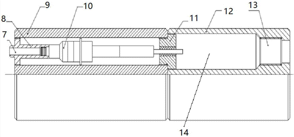
[0031] see Figure 4 The frequency difference infrasonic generator is installed above the wellhead and connected to the control unit. The control unit is connected to the microphone at the wellhead and the remote host computer and oscilloscope r...


PUM


Abstract

Provided is a method for measuring the dynamic liquid surface of an oil well with a frequency difference infrasonic wave generator. The method for measuring the dynamic liquid surface of the oil well with the frequency difference infrasonic wave generator comprises the following steps of (1) pre-installing echo machines at the inner side of each casing coupling and the outer side of each tubing coupling respectively; (2) installing the frequency difference infrasonic wave generator above the mouth of the oil well, and enabling the frequency difference infrasonic wave generator to be connected to a control unit which is connected with a microphone at the mouth of the oil well and an upper computer and an oscilloscope at a remote end respectively; (3) sending a signal to the control unit through the upper computer, transmitting a generated infrasonic wave to the downhole, then receiving reflected waves returned by a downhole echo machine and the dynamic liquid surface through the microphone at the mouth of the oil well, and then converting the reflected waves into electric signals so as to display the electric signals on the oscilloscope; (4) transmitting the electric signals to an AD sampling chip, obtaining the height of the dynamic liquid surface through calculation with the chip, and sending results to the upper computer. The method for measuring the dynamic liquid surface of the oil well with the frequency difference infrasonic wave generator has the advantages of being high in safety, low in operation cost and construction intensity, controllable in process, small in measurement error and capable of achieving real-time, continuous, remote and unmanned monitoring of the dynamic liquid surface of the oil well.

Description

technical field [0001] The invention relates to the technical field of oil and gas field development, in particular to a method for measuring the dynamic liquid level of an oil well with a frequency difference type infrasonic wave generator. Background technique [0002] In the process of oil field production, the dynamic liquid level indicates the height of the annular liquid level between the tubing and casing of the pumping well from the bottom of the well. It is usually used to judge the level of formation pressure and is a key indicator reflecting the formation's liquid supply capacity. It is an important basis for determining a reasonable sinking degree and formulating a reasonable working system. At present, the methods of measuring the dynamic liquid level include pressure sensor testing, emptying shells, and pneumatic sound source testing. Due to the problems of complicated operation, relatively poor safety and reliability in pressure sensor testing and emptying she...

Claims


Application Information

Patent Timeline
IPC IPC(8): E21B47/047E21B47/14
CPCE21B47/14E21B47/047
Inventor 周德胜杨华张楠
Owner XI'AN PETROLEUM UNIVERSITY
Why Eureka
Try Eureka