

Winding-type cell
A winding type battery technology, applied in the direction of circuits, electrical components, secondary batteries, etc., can solve the problems of waste of separator 3, reduce the energy density of batteries, increase the thickness of batteries, etc., to save costs and realize automation The effect of production and energy density improvement
- Summary
- Abstract
- Description
- Claims
- Application Information
AI Technical Summary
Problems solved by technology
Method used
Image

Examples
Embodiment Construction
[0029] The wound battery core of the present invention will be described in detail below with reference to the accompanying drawings.
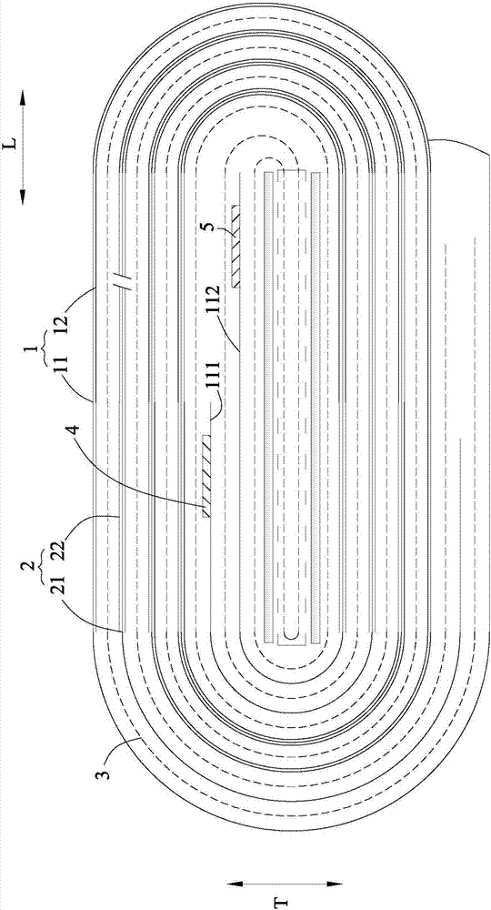
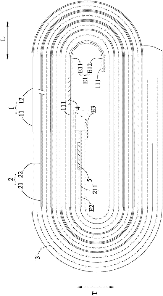
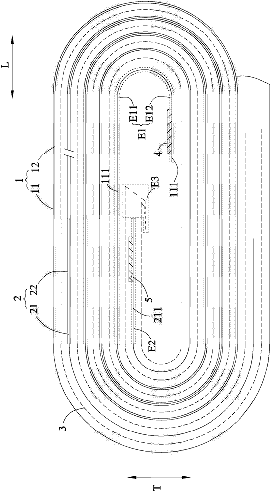
[0030] refer to Figure 2 to Figure 5 , according to the present invention, the winding type electric core comprises: a first pole piece 1 having a first current collector 11 and a first active material layer 12 coated on at least one surface of the first current collector 11; a second pole piece 2 , has a second current collector 21 and a second active material layer 22 coated on at least one surface of the second current collector 21, and the second winding start segment E2 of the second pole piece 2 has an uncoated second active material The blank second current collector 211 of the layer 22; the isolation film 3 is arranged between the first pole piece 1 and the second pole piece 2, so as to isolate the first pole piece 1 and the second pole piece 2; the first pole piece 4, electrically connected to the first current collector 11; the sec...
PUM
 Abstract
Description
Claims
Application Information