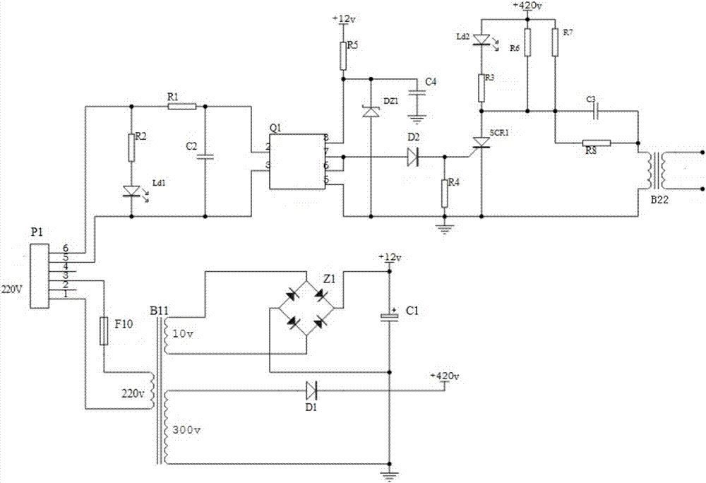
Novel shock wave trigger circuit

A trigger circuit and shock wave technology, applied in medical science, surgery, etc., can solve the problems of easy leakage trigger, small output current, high price, etc., and achieve the effect of simple circuit, stable trigger, and stable and reliable trigger pulse

Pending Publication Date: 2017-10-31
上海卡姆南洋医疗器械股份有限公司
View PDF0 Cites 1 Cited by
  • Summary
  • Abstract
  • Description
  • Claims
  • Application Information

AI Technical Summary

Problems solved by technology

[0002] The existing shock wave trigger circuit generally adopts the high-voltage package output by the TV line, the output current is small, and it is

Method used


Image

  • Novel shock wave trigger circuit

Examples


Embodiment Construction

[0016] The following will clearly and completely describe the technical solutions in the embodiments of the present invention with reference to the accompanying drawings in the embodiments of the present invention. Obviously, the described embodiments are only some, not all, embodiments of the present invention. Based on the embodiments of the present invention, all other embodiments obtained by persons of ordinary skill in the art without creative efforts fall within the protection scope of the present invention.

[0017] It should be noted that, in the case of no conflict, the embodiments of the present invention and the features in the embodiments can be combined with each other.

[0018] refer to figure 1 As shown, the shock wave trigger circuit of the present invention includes a trigger transformer B22, a power transformer B11, a bridge rectifier Z1, a thyristor SCR1, a photocoupler Q1, a first resistor R1, a second resistor R2, a third resistor R3, and a fourth resistor...


PUM


Abstract

The invention relates to a novel shock wave trigger circuit, including a trigger transformer, a power transformer, a bridge rectifier, a silicon controlled rectifier, a photoelectric coupler, a resistor, a capacitor, a silicon controlled rectifier and a diode, etc. In the part, the trigger pulse signal controls the conduction of the thyristor through the photocoupler to generate a trigger high voltage. Compared with the prior art, the beneficial effect of the present invention lies in that the trigger transformer is controlled by a silicon controlled rectifier to generate a trigger high voltage, the trigger pulse is stable and reliable, there is no leakage or burst, the circuit is simple, the trigger is stable, and it is used for extracorporeal shock wave breaking stone machine.

Description

technical field [0001] The invention relates to a trigger circuit, in particular to a novel shock wave trigger circuit. Background technique [0002] The existing shock wave trigger circuit generally adopts the high-voltage package output by the TV line, the output current is small, and it is easy to leak the trigger; or the car igniter is used, the product is large in size, high in price, and its use is limited, but there is no better solution. Contents of the invention [0003] In view of this, the object of the present invention is to provide a shock wave trigger circuit to solve the deficiencies in the prior art. [0004] In order to achieve the above object, the purpose of the present invention is achieved through the following technical solutions: [0005] A shock wave trigger circuit, including a trigger transformer, a power transformer, a bridge rectifier, a thyristor, a photocoupler, a first resistor, a second resistor, a third resistor, a fourth resistor, a fift...

Claims


Application Information

Patent Timeline
IPC IPC(8): A61B17/225
CPCA61B17/225
Inventor 孔庆园
Owner 上海卡姆南洋医疗器械股份有限公司
Why Eureka
Try Eureka