Triggering device and method for silicon controlled rectifier in single-phase alternating current circuit
A single-phase AC and trigger device technology, applied in the field of electricity, can solve problems such as low stability, complex overall system structure, and high cost, and achieve the effects of improving stability, realizing stable adjustment, and low cost
- Summary
- Abstract
- Description
- Claims
- Application Information
AI Technical Summary
Problems solved by technology
Method used
Image
Examples
Embodiment 1
[0038] In Embodiment 1 of the present invention, the specific structure of the trigger device and the specific working process for realizing the stable adjustment of the conduction angle and the stable trigger of the thyristor are described in detail.
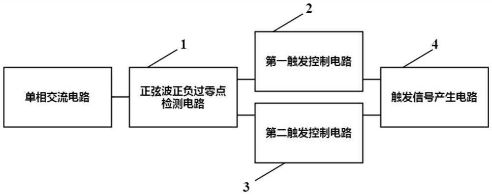
[0039] Such as figure 1 As shown, it is a structural schematic diagram of the trigger device of the thyristor in the single-phase AC circuit in the present invention. The trigger device includes a sine wave positive and negative zero-crossing detection circuit 1 , a first trigger control circuit 2 , a second trigger control circuit 3 and a trigger signal generation circuit 4 . in,
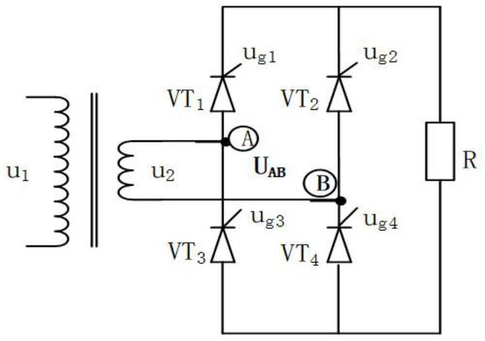
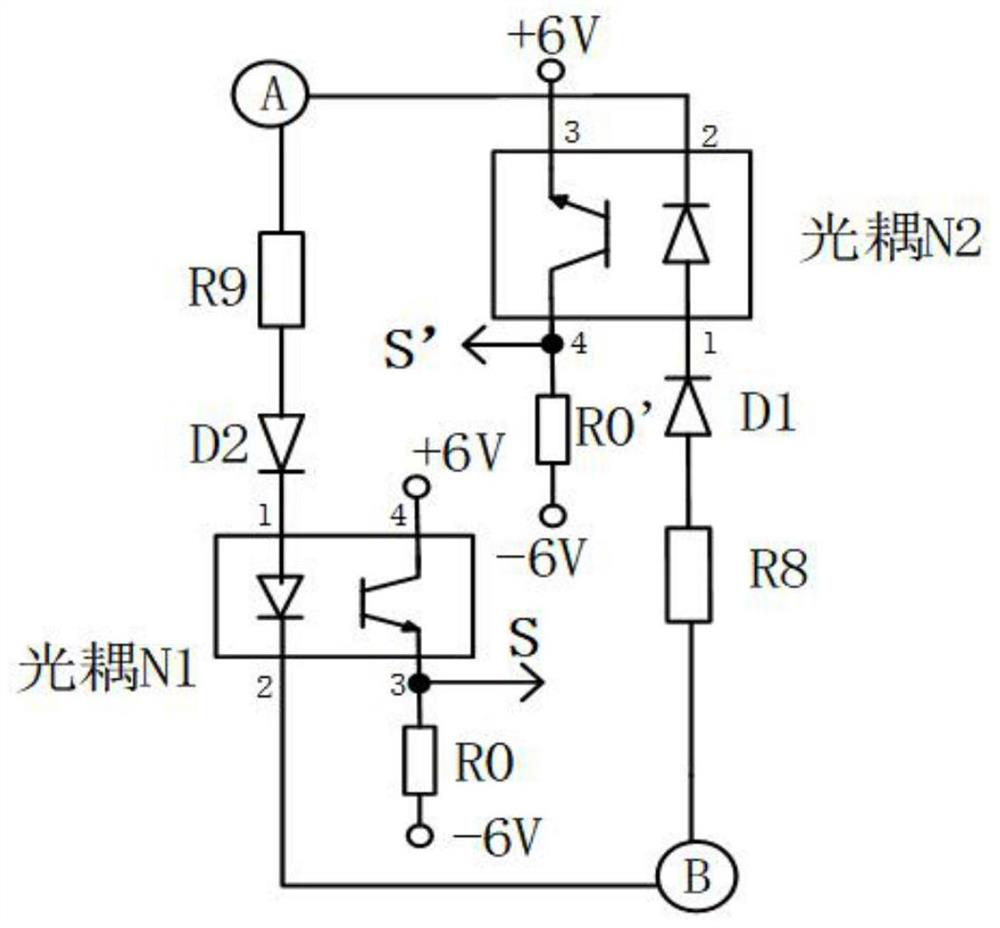
[0040]The sine wave positive and negative zero-crossing detection circuit 1 is connected between the first detection point and the second detection point of the single-phase AC circuit, and is used to detect the zero-crossing signal in the single-phase AC circuit; the zero-crossing signal includes the first detection signal and the second detectio...
Embodiment 2
[0120] Such as Figure 8 As shown, it is a flow chart of the method for triggering the thyristor in the single-phase AC circuit in the present invention, wherein S1-S4 correspond to each step in the method.
[0121] The specific process includes:
[0122] S1. Connect the sine wave positive and negative zero-crossing detection circuit 1 between the first detection point and the second detection point of the single-phase AC circuit, and output the first detection at the first output terminal of the sine wave positive and negative zero-crossing detection circuit 1 signal, the second detection signal is output at the second output end of the sine wave positive and negative zero-crossing detection circuit 1;
[0123] S2. Electrically connect the first trigger control circuit 2 to the first output terminal, convert the first detection signal into the first trigger control signal and output it at the output terminal of the first trigger control circuit 2; connect the second trigger ...
PUM
 Abstract
Description
Claims
Application Information
 - R&D
- Intellectual Property
- Life Sciences
- Materials
- Tech Scout
- Unparalleled Data Quality
- Higher Quality Content
- 60% Fewer Hallucinations
Browse by: Latest US Patents, China's latest patents, Technical Efficacy Thesaurus, Application Domain, Technology Topic, Popular Technical Reports.
© 2025 PatSnap. All rights reserved.Legal|Privacy policy|Modern Slavery Act Transparency Statement|Sitemap|About US| Contact US: help@patsnap.com


