
relay

A technology of relays and electromagnets, applied in the field of electronic control devices, can solve problems such as inconsistency in economic benefits, delay in construction period, and increase in working hours and costs

Active Publication Date: 2020-04-28
厦门台松精密电子有限公司
View PDF6 Cites 0 Cited by
  • Summary
  • Abstract
  • Description
  • Claims
  • Application Information

AI Technical Summary

Problems solved by technology

[0008] 1. Because the base uses jacks to provide pins and joints, the directionality of the pins in assembly is limited, and the combination of pins due to the limited direction will be inconsistent with the assembly direction of the front and rear processes on the automated machine and cannot be coherent Complete assembly at one time, resulting in complex assembly process and troublesome manufacturing
[0009] 2. Due to the inability to complete the assembly of the pins on the automated machine in one go, manufacturing troubles are caused, and further delays in the construction period and increase in man-hour costs are not in line with economic benefits.
[0010] Therefore, how to improve the creation of the above-mentioned "relay component" structure that cannot be assembled on an automated machine at one time, resulting in troubles and inconveniences in manufacturing, and the resulting delay in the construction period and increase in labor costs, etc. The Difficulties of Inventing What You Want to Solve

Method used


Image

  • relay
  • relay
  • relay

Examples


Embodiment Construction

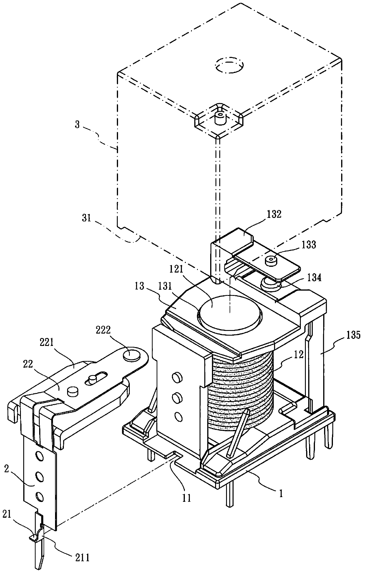
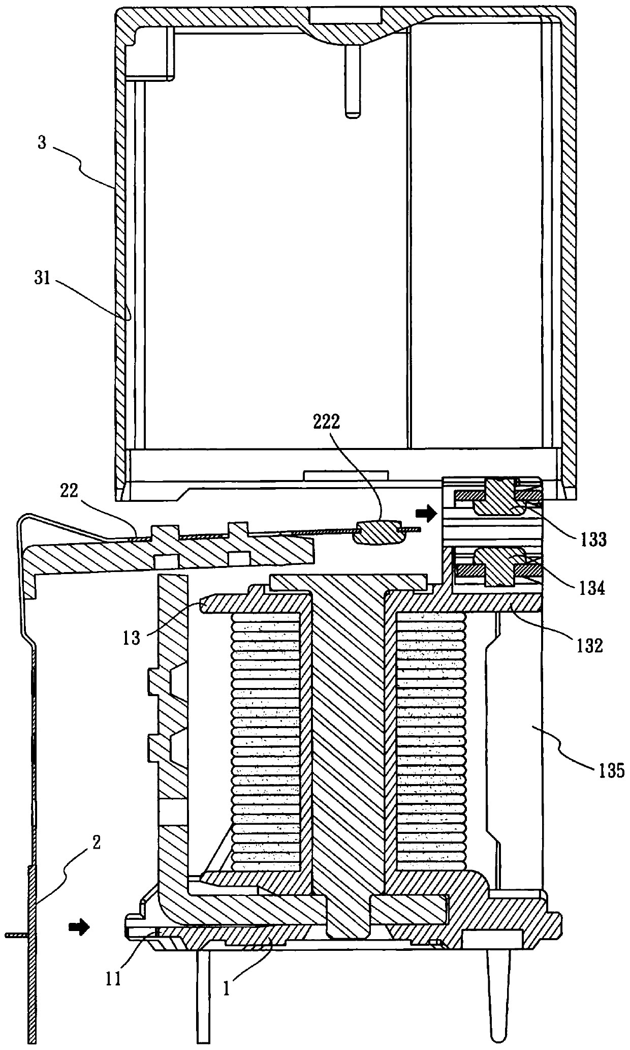
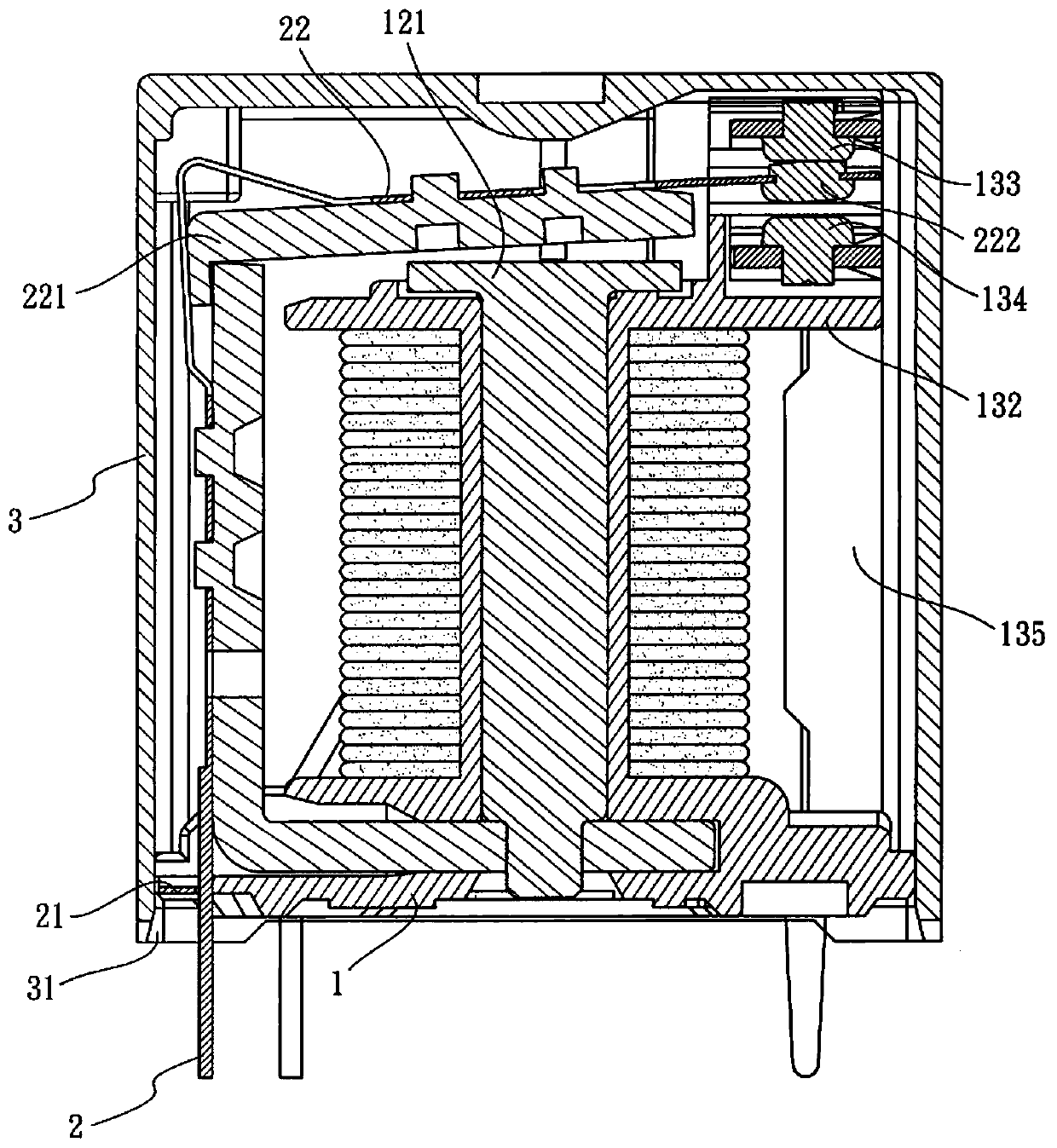
[0043] see Figure 1 to Figure 5 The present invention shown is a relay comprising: a base 1 having a notch 11 on the peripheral side. And a pin 2 , which has a protruding piece 21 , the pin 2 is assembled on the notch 11 of the base 1 and one end passes through the notch 11 , and the protruding piece 21 covers the notch 11 .

[0044] According to the above structure combination description, as mentioned above Figure 1 to Figure 5 In the present invention, the base 1 is combined with an electromagnet 12 and a control seat 13. The electromagnet 12 has a magnetic end 121 and is located at an end away from the base 1. The control seat 13 has a control part 132. The control seat 13 Set on the magnetic end 121 , the control part 132 is provided with an upper contact 133 and a lower contact 134 , the lower contact 134 is located on the lower side of the upper contact 133 . Secondly, the pin 2 has a bent section 22 extending toward the control base 13, the bent section 22 is provi...


PUM


Abstract

The invention relates to a relay. The relay comprises a base, a pin and an outer cover, wherein the base is provided with a gap formed in a peripheral side, the pin is provided with a convex piece and is assembled in the gap of the base, one end of the pin penetrates out of the gap, the convex piece covers and shields the gap, the outer cover is provided with an accommodating groove, a groove opening of the accommodating groove of the outer cover covers the base and the pin, and the peripheral side of the base, the convex piece of the pin and the groove opening of the accommodating groove are fixed by coating with an adhesive. Combination without directional limitation is provided for the pin by means of the gap at the peripheral side of the base, the assembly of the base and pin is facilitated, combination on an automatic machine table at a time can be achieved, and the improvement of simplifying the relay manufacturing and assembly process is effectively achieved.

Description

technical field [0001] The invention relates to the technical field of electronic control devices, in particular to a relay. Background technique [0002] The relay is a control component commonly used in daily life. When the conditions are met, the control relay has the function of closing or opening, and is often used in protection actions such as automatic control. Therefore, the use of relays is extremely extensive, and there are many types of relays in their selection. For example, reed relays are used in communication, testing, and other safety systems; high-voltage relays are used in high-voltage measuring instruments, medical equipment, cable testing machines, etc.; automotive relays are used in automotive equipment with circuit boards or quick connectors, etc. Type automotive relays; or circuit board relays commonly used with circuit boards, which can be used in communications, electronic instruments, automatic control, home appliances, etc., and installed on vario...

Claims


Application Information

Patent Timeline
Patent Type & Authority Patents(China)
IPC IPC(8): H01H50/14H01H50/02
CPCH01H50/02H01H50/14
Inventor 叶家昇
Owner 厦门台松精密电子有限公司
Learn More