Micromotor Using Multilayer Annular Piezoelectric Ceramics

A technology of piezoelectric ceramics and micro-motors, applied in the field of micro-motors, can solve problems such as low motor stability, increased motor volume, and increased influence, and achieve good stability, stable high-torque output, and low-voltage driving performance Effect

Active Publication Date: 2019-09-13
北京派和智能装备技术有限公司
View PDF5 Cites 0 Cited by
  • Summary
  • Abstract
  • Description
  • Claims
  • Application Information

AI Technical Summary

Problems solved by technology

[0005] At present, the existing piezoelectric motors are driven by single-layer piezoelectric ceramics. To generate a certain amount of driving force and driving speed, a relatively large driving voltage (generally about 200V / mm) is required. However, for micro motors, the size of the motor itself is small, and the general application occasions are some small electronic products. At this time, the drive of the motor is required. The voltage should be as small as possible, as far as possible to use CMOS devices to directly drive (the driving voltage is about 5V), and the relatively large driving voltage will also increase the risk factor when the motor is used, and the impact of high voltage on the low voltage end will increase and other adverse effects
At this time, it is difficult to meet the requirements by using traditional single-layer bulk piezoelectric ceramics.
[0006] Moreover, most existing piezoelectric motors are driven by dual-phase circuits with the same frequency. For dual-phase circuits, it is difficult to ensure that the frequency of the dual-phase circuits remains strictly equal during the entire working period of the motor. Accompanied by processing errors, errors of circuit electronic components, temperature drift and other problems, the stability of the motor will be low
[0007] In addition, in the prior art, in order to realize the high torque output of the piezoelectric motor, it is usually necessary to add an additional circuit structure, which will easily lead to an increase in the size of the motor, and it is difficult to achieve high torque output for a micro motor with a small volume.

Method used


Image

  • Micromotor Using Multilayer Annular Piezoelectric Ceramics
  • Micromotor Using Multilayer Annular Piezoelectric Ceramics
  • Micromotor Using Multilayer Annular Piezoelectric Ceramics

Examples


Embodiment Construction

[0037] In order to make the technical problems, technical solutions and advantages to be solved by the present invention clearer, the following will describe in detail with reference to the drawings and specific embodiments.

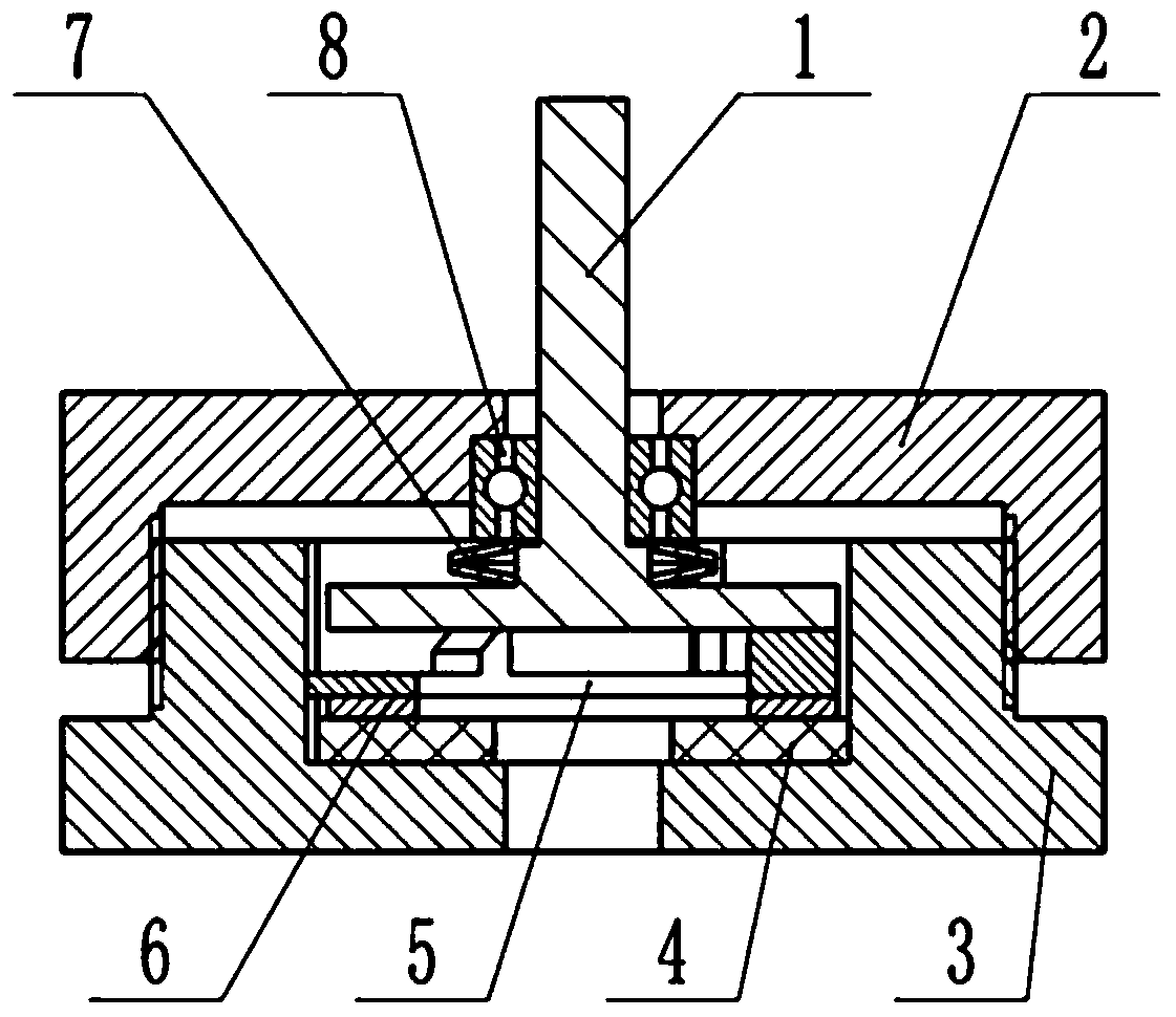
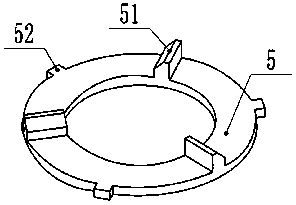
[0038] On the one hand, the present invention provides a kind of micromotor that adopts multi-layer annular piezoelectric ceramics, such as figure 1 As shown, it includes a housing, the interior of the housing is provided with a stator and a rotor 1, the stator includes a stator ring 5, and one side of the stator ring 5 is evenly provided with at least two contacts 51 for driving the rotor 1 along the circumferential direction , the other side is provided with a multi-layer annular piezoelectric ceramic 6 for driving the movement of the stator ring 5, wherein:

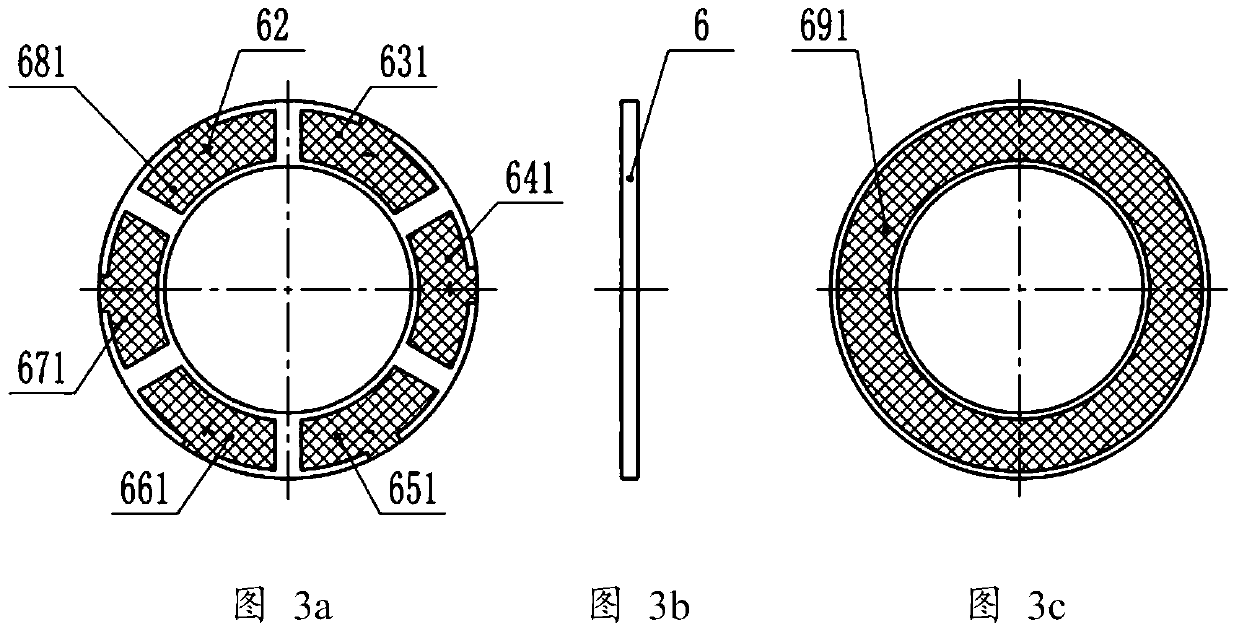
[0039] The multilayer annular piezoelectric ceramics 6 are evenly divided into even-numbered partitions, the polarization directions of two adjacent partitions are opposite, and the energization ...


PUM

PropertyMeasurementUnit
thicknessaaaaaaaaaa

Abstract

The invention discloses a micromotor employing multilayer annular piezoelectric ceramic, and belongs to the field of a piezoelectric driver, a small and special electrical machine and a miniature driver. The micromotor comprises a shell, wherein a stator and a rotor are arranged in the shell, the stator comprises a stator round ring, contacts are arranged at one side of the stator round ring, the multilayer annular piezoelectric ceramic is arranged at the other side of the stator round ring, the multilayer annular piezoelectric ceramic is uniformly divided into an even number of partition regions, the polarization directions of two adjacent partition regions are opposite, the energization directions of two adjacent layers of annular piezoelectric ceramic are opposite, a positive electrode and a negative electrode are arranged on an upper surface and a lower surface of the multilayer annular piezoelectric ceramic, the positive electrode is also divided into an even number of partition regions which are in one-to-one correspondence to the partition regions of the multilayer annular piezoelectric ceramic, the number of the partition regions of the multilayer annular piezoelectric ceramic are two times of the number of the contacts, and the positions of the contacts are corresponding to empty regions between the partition regions of two adjacent electrodes. Compared with the prior art, the micromotor has the characteristics of low-voltage driving performance, high stability and large torque output.

Description

technical field [0001] The invention relates to the fields of piezoelectric drivers, micro-special motors and micro-drivers, in particular to a micromotor using multi-layer annular piezoelectric ceramics. Background technique [0002] Micro motors generally refer to motors with small size (overall structural size or size in a certain direction), high positioning accuracy (or repeat positioning accuracy), low energy consumption, and high power density. At present, more and more researches and engineering applications have created an urgent demand for micro motors, while traditional wound electromagnetic motors are difficult to miniaturize due to their complex structures. In the late 1980s, researchers used silicon micromachining technology to manufacture electrostatic micromotors with a diameter of several hundred microns, which triggered a revolution in microactuators in the field of microelectromechanical systems (MEMS, Micro Electromechanical System). . However, although...

Claims


Application Information

Patent Timeline
Patent Type & Authority Patents(China)
IPC IPC(8): H02N2/10H02N2/12
Inventor 赵艳强范杨雷
Owner 北京派和智能装备技术有限公司
Why Eureka
Try Eureka