Self-propelled building tubular product ring-cutting device

A technology for installing rings and cutting rings, which is applied in the direction of pipe shearing devices, shearing devices, and shearing machine equipment, etc., can solve the problems of cutting blade jamming, cutting distortion, and cutting cycle benches, etc., and achieve fast and stable operation and cutting The surface is neat and the effect of cutting process blocks

Inactive Publication Date: 2017-11-03
黄瀚
View PDF0 Cites 21 Cited by
  • Summary
  • Abstract
  • Description
  • Claims
  • Application Information

AI Technical Summary

Problems solved by technology

[0002] In building use, materials are often processed, but large-scale pipe cutting devices are often time-consuming and labor-intensive, requiring frequent repeated cutting operations, which makes the device's operating efficiency low, and the transmission structure is poor, not stable and efficient, Restricts its popularization and application in actual production
[0003] In order to solve the above-mentioned problems, the present invention is proposed, which overcomes the problem of the traditional large-scale pipe cutting due to the imperfect design of the device structure itself, resulting in uneven cutting surface, serious cutting distortion, and cutting cycle bench problems. The cutting device for pipe construction, due to the low efficiency of mechanical transmission, caused the problem that the cutting blade was stuck and damaged the power components during the pipe cutting process, which improved the traditional large-scale pipe construction cutting device. For the next cutting, time-consuming and labor-intensive problems, by integrating the mobile installation module and the rotary ring cutting module, the present invention has the advantages of novel structure, compact appearance, efficient transmission, fast and stable operation, neat cutting surface, cutting process blocks, etc.

Method used


Image

  • Self-propelled building tubular product ring-cutting device
  • Self-propelled building tubular product ring-cutting device
  • Self-propelled building tubular product ring-cutting device

Examples


Embodiment Construction

[0018] The following will clearly and completely describe the technical solutions in the embodiments of the present invention with reference to the accompanying drawings in the embodiments of the present invention. Obviously, the described embodiments are only some, not all, embodiments of the present invention. Based on the embodiments of the present invention, all other embodiments obtained by persons of ordinary skill in the art without making creative efforts belong to the protection scope of the present invention.

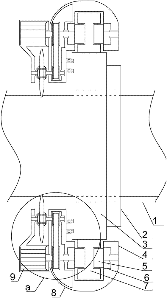
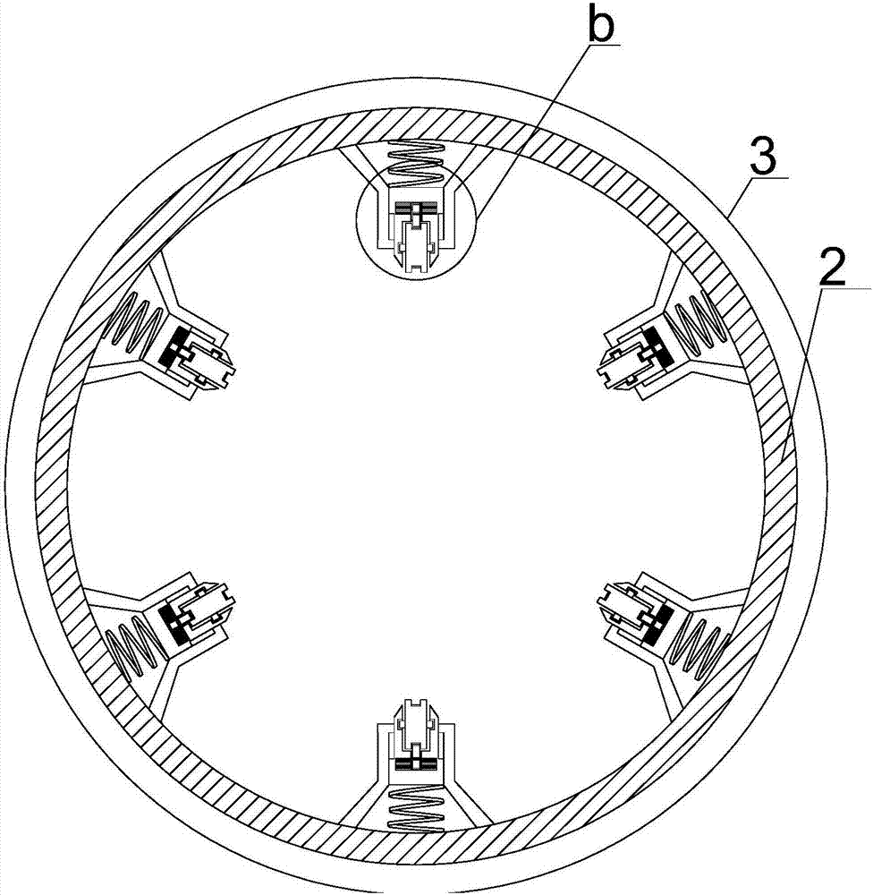
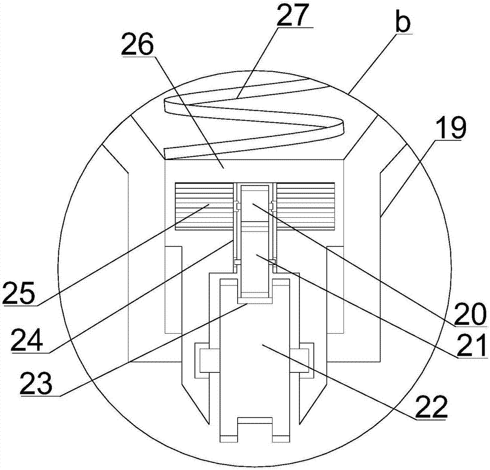
[0019] see Figure 1~4 , in an embodiment of the present invention, a self-propelled installation type ring cutting device for building pipes, including a mobile installation module and a rotary ring cutting module, the mobile installation module includes a supporting mobile installation cylinder 3 wrapped and arranged on the outside of the pipe to be processed 1, The inner side of the support mobile installation cylinder 3 is provided with a limit installatio...


PUM


Abstract

The invention discloses a self-propelled installation type ring cutting device for building pipes, which includes a mobile installation module and a rotary ring cutting module. The inner side is provided with a limited installation ring to the right, and the inner side of the limited installation ring is provided with six sets of clamping and moving installation mechanisms at equal angles. The rotary ring cutting module is arranged on the outside of the supporting mobile installation cylinder. The rotating mechanism on the outside of the mobile installation cylinder and the power ring cutting mechanism installed at the same angle on the left end thereof, the rotation mechanism includes the I-shaped rotating guide rail installed on the outside of the supporting mobile installation cylinder, and the outer side of the I-shaped rotating guide rail is provided with a package and a rotating support Installing the cover, the invention has the advantages of novel structure, compact appearance, high-efficiency transmission, fast and stable operation, neat cutting surface, and cutting process blocks.

Description

technical field [0001] The invention relates to a building construction infrastructure construction machine, in particular to a self-propelled installation type ring cutting device for building pipes. Background technique [0002] In building use, materials are often processed, but large-scale pipe cutting devices are often time-consuming and labor-intensive, requiring frequent repeated cutting operations, which makes the device's operating efficiency low, and the transmission structure is poor, not stable and efficient, It restricts its popularization and application in actual production. [0003] In order to solve the above-mentioned problems, the present invention is proposed, which overcomes the problem of the traditional large-scale pipe cutting due to the imperfect design of the device structure itself, resulting in uneven cutting surface, serious cutting distortion, and cutting cycle bench problems. The cutting device for pipe construction, due to the low efficiency ...

Claims


Application Information

Patent Timeline
Patent Type & Authority Applications(China)
IPC IPC(8): B23D21/04
CPCB23D21/04
Inventor 黄瀚
Owner 黄瀚
Why Eureka
Try Eureka