Positioning device for rapid cutting of annular parts

A rapid cutting and positioning device technology, which is applied to positioning devices, metal processing machinery parts, clamping, etc., can solve the problems that the adjustment of positioning devices is too dependent on experience, the positioning accuracy is difficult to adjust and control, and the fixture adjustment time is long, etc., to improve Cutting efficiency, strong size applicability, easy disassembly and assembly

Inactive Publication Date: 2017-11-03
UNIV OF SHANGHAI FOR SCI & TECH
View PDF7 Cites 0 Cited by
  • Summary
  • Abstract
  • Description
  • Claims
  • Application Information

AI Technical Summary

Problems solved by technology

[0008] 1) It takes a long time to adjust the fixture, and the positioning accuracy is difficult to adjust and control
[0009] 2) The adaptability is poor, the adjustment of the positioning device is too dependent on experience, and the accuracy is difficult to control
[0010] 3) It takes a long time and cannot improve efficiency

Method used


Image

  • Positioning device for rapid cutting of annular parts
  • Positioning device for rapid cutting of annular parts
  • Positioning device for rapid cutting of annular parts

Examples


Embodiment

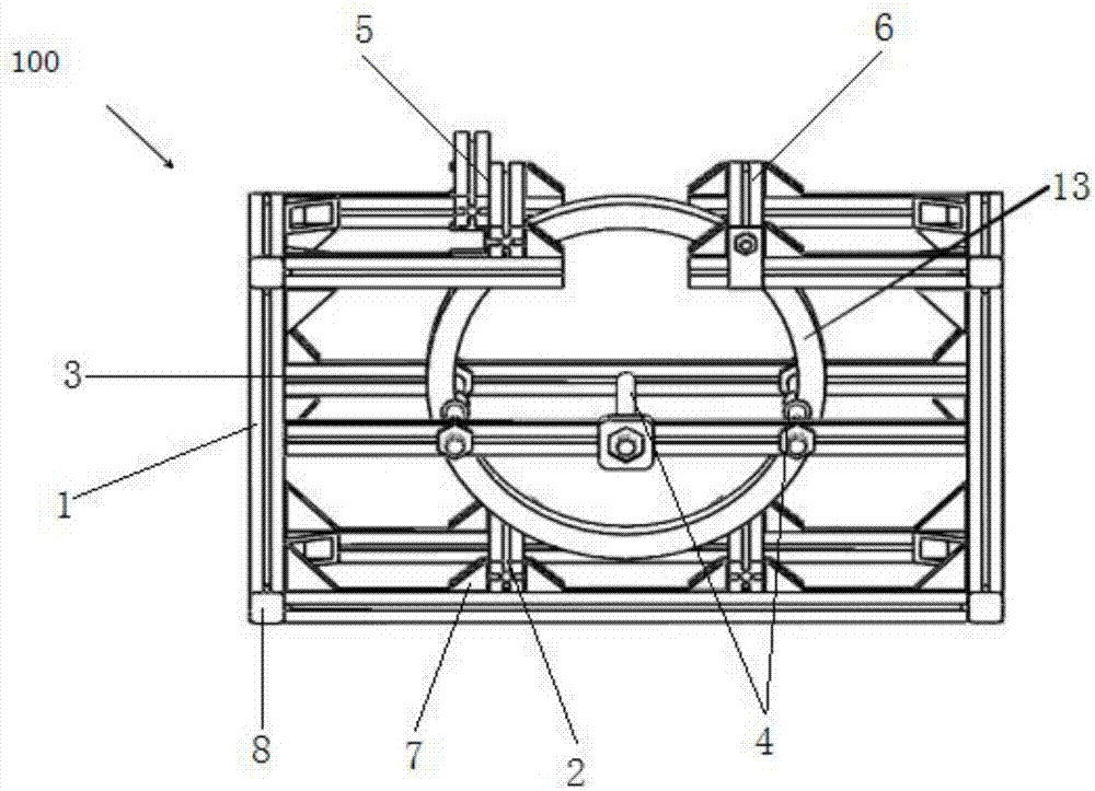
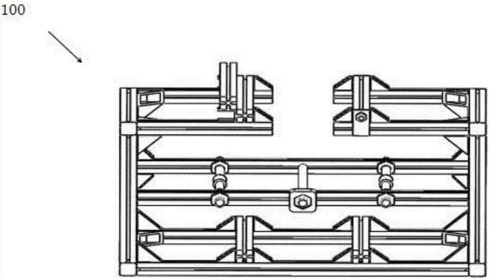
[0030] figure 1 It is a schematic diagram of the structure when cutting the workpiece in the embodiment of the present invention, figure 2 It is a schematic diagram of the overall frame structure in the embodiment of the present invention.

[0031] Such as figure 1 and 2 As shown, a positioning device for quickly cutting ring-shaped parts in this embodiment is used to position the workpiece to be cut before cutting, including: a frame 1, a first truss 2, a perforated truss 3, a positioning rod 4, two Root second truss 5, third truss 6, special triangle iron 7, square closed cover 8.

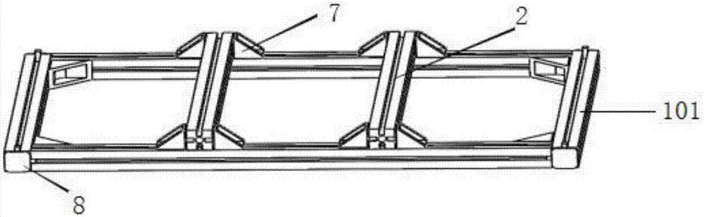
[0032] The special triangle iron 7 is arranged at the joint between the frame 1 and the truss, and is used for fixing the truss.

[0033] The square closure cover 8 is fixedly connected to the four corners of the bottom frame 101 and the top frame 103 .

[0034] image 3 It is a structural schematic diagram of the bottom device in the embodiment of the present invention.

[0035] Such as ...


PUM


Abstract

The invention discloses a positioning device for quickly cutting ring-shaped parts, which is used for positioning the workpiece to be cut before cutting, comprising: a frame, in the form of a rectangle, including a bottom frame, a vertical frame and a top frame; a first truss set At one-third of the bottom frame, it is used to fix the bottom end of the workpiece to be cut; the perforated truss includes the first perforated truss and the second perforated truss placed in parallel, the first perforated truss and the second perforated truss Both ends of the truss are fixed on the vertical frames on both sides, and the first perforated truss and the second perforated truss have threaded holes; positioning rods include short positioning rods and long positioning rods, short positioning rods and long positioning rods The rods pass through the threaded holes and are set between the first truss with holes and the second truss with holes to fix the middle part of the workpiece to be cut; the two second trusses and the third truss are respectively set on the left side of the opening of the top frame. The side and the right side of the opening are used to fix the top of the workpiece to be cut.

Description

technical field [0001] The invention relates to a repair tool for ring-shaped sleeve parts in the fields of automobiles and aerospace, in particular to a positioning device for quickly cutting ring-shaped parts. Background technique [0002] At present, when producing motor stators in China, related companies that produce motors usually conduct failure analysis on failed products and separate and extract recyclable raw materials according to the cause of failure for the purpose of saving costs. When the stator aluminum sleeve fails and the rest is intact, it is usually necessary to cut off the aluminum sleeve, and then reuse the stator return line. Due to the high price of purchased large-scale professional automatic cutting equipment, maintenance is complicated. In order to meet the needs of cost saving, efficiency improvement and fast cutting, this patent mainly meets the cutting of ring-shaped parts. In the process of cutting ring-shaped parts, due to the close connecti...

Claims


Application Information

Patent Timeline
Patent Type & Authority Applications(China)
IPC IPC(8): B23Q3/06
CPCB23Q3/062
Inventor 曹萌仲梁维高甜
Owner UNIV OF SHANGHAI FOR SCI & TECH
Why Eureka
Try Eureka