Textile cloth rolling device capable of changing cloth roller quickly

A cloth roll, fast technology, applied in the field of textile processing, can solve the problems of low tape winding efficiency, poor connection effect, crushing workers, etc., to improve the speed of installation and disassembly work, improve stability and Work efficiency, improve the effect of the processing process

Inactive Publication Date: 2017-11-03
姚莉萍
View PDF8 Cites 5 Cited by
  • Summary
  • Abstract
  • Description
  • Claims
  • Application Information

AI Technical Summary

Problems solved by technology

[0002] After the cloth tape is weaved, dyed and other processes, the cloth tape needs to be rolled up so that the rolled cloth tape is convenient for packaging and transportation. However, the existing cloth tape winding device has a complex structure and troublesome operation. The rolling efficiency is low and the quality is poor. For example, the rolling bar of the cloth rolling roller is connected to the transmission wheel by being embedded in the slot of the transmission wheel, and the connection effect is poor. High, the cloth roll rod is in danger of detaching from the transmission wheel. In addition, the cloth roll rod is manually removed in the current cloth unloading operation. Since the cloth on the cloth roll has a considerable weight, there is a danger of crushing the workers.

Method used


Image

  • Textile cloth rolling device capable of changing cloth roller quickly
  • Textile cloth rolling device capable of changing cloth roller quickly
  • Textile cloth rolling device capable of changing cloth roller quickly

Examples


Embodiment Construction

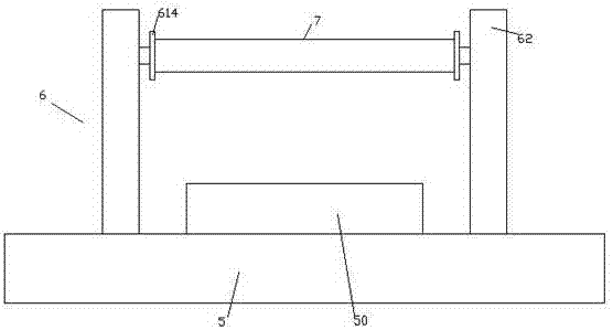
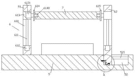
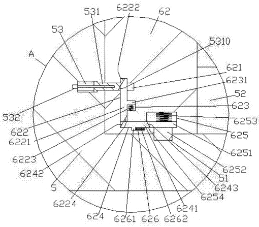
[0022] Such as Figure 1-Figure 6 As shown, a textile cloth rolling device of the present invention, which can quickly replace cloth rolling rollers, includes a base 5 and a support assembly 6 arranged on the top of the base 5, and a first guide is provided on the top end surface of the right side of the base 5. groove 52, the first guide groove 52 is provided with a guide rod 521 extending left and right, the support assembly 6 is composed of a first support frame 61 and a second support frame 62, and the first support frame 61 is fixed on the On the top end surface of the left side of the base 5, the second support frame 62 is located on the right side of the base 5 and the bottom extends into the first guide groove 52, and the bottom end surface of the second support frame 62 is provided with a first Sliding chamber 625, the first sliding chamber 625 is slidingly connected with a first sliding block 6251, and the bottom of the first sliding block 6251 is fixed with a lockin...


PUM


Abstract

The invention discloses a textile cloth rolling device capable of changing a cloth roller quickly. The textile cloth rolling device capable of changing the cloth roller quickly comprises a pedestal and a supporting assembly arranged at the top of the pedestal; a first guide groove is formed in the end face of the top of the right side of the pedestal; a guide rod which extends left and right is arranged in the first guide groove; the supporting assembly consists of a first supporting frame and a second supporting frame; the first supporting frame is fixed on the end face of the top of the left side of the pedestal; the second supporting frame is positioned on the right side of the pedestal, and the bottom of the second supporting frame stretches into the first guide groove; a first sliding cavity is formed in the end face of the bottom of the second supporting frame; the first sliding cavity is in sliding and cooperative connection with a first sliding block; a locking block which runs through the end face of the bottom of the second supporting frame is fixedly arranged at the bottom of the first sliding block; a second sliding cavity which extends up and down is formed in the second supporting frame on the left side of the first sliding cavity; and a second guide groove is formed in the inner wall of the right side of the second sliding cavity. The textile cloth rolling device capable of changing the cloth roller quickly has a simple structure, can realize rapid locking and mounting as well as automatic control unlocking, increases the speed of mounting work and dismounting work of the cloth roller, can automatically ascend and descend a cloth roll, and improves the operation safety.

Description

technical field [0001] The invention relates to the technical field of textile processing, in particular to a textile cloth rolling device whose cloth rolling rollers can be quickly replaced. Background technique [0002] After the cloth tape is weaved, dyed and other processes, the cloth tape needs to be rolled up so that the rolled cloth tape is convenient for packaging and transportation. However, the existing cloth tape winding device has a complex structure and troublesome operation. The rolling efficiency is low and the quality is poor. For example, the rolling bar of the cloth rolling roller is connected to the transmission wheel by being embedded in the slot of the transmission wheel, and the connection effect is poor. High, the cloth roll rod is in danger of detaching from the transmission wheel. In addition, the cloth roll rod is manually removed in the current cloth unloading operation. Since the cloth on the cloth roll has a considerable weight, there is a danger...

Claims


Application Information

Patent Timeline
Patent Type & Authority Applications(China)
IPC IPC(8): B65H18/02B65H19/30
CPCB65H18/028B65H19/30B65H2301/418B65H2701/1133B65H2701/174
Inventor 姚莉萍
Owner 姚莉萍
Why Eureka
Try Eureka