Plate type aerating spreading device capable of automatic cleaning

An automatic cleaning and diffusion device technology, applied in the direction of sustainable biological treatment, water aeration, special treatment goals, etc., can solve the problems of affecting the aeration effect and blockage of aeration diffusion parts

Inactive Publication Date: 2017-11-03
陈美廷
View PDF0 Cites 0 Cited by
  • Summary
  • Abstract
  • Description
  • Claims
  • Application Information

AI Technical Summary

Problems solved by technology

Existing aeration equipment often clogs the aeration diffusion parts due to factors such as dirt sedimentation in the...

Method used


Image

  • Plate type aerating spreading device capable of automatic cleaning

Examples


Embodiment 1

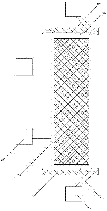
[0014] like figure 1 A plate type aeration diffusion device that can realize automatic cleaning treatment is shown, which includes a diffusion frame 1, and a diffusion packing layer 2 arranged inside the diffusion frame 1; the lower end surface of the diffusion packing layer 2 is connected with a plurality of The lifting motor 3 arranged outside the diffusion frame, a plurality of lifting tanks 4 are arranged on the inner wall of the diffusion frame 1, a plurality of lifting end bodies 5 are arranged on the side end surface of the diffusion packing layer 2, and a plurality of The lifting end body 5 and the plurality of lifting tanks 4 correspond to each other one by one, and each lifting end body 5 extends into the corresponding lifting tank body 4;

[0015] As an improvement of the present invention, at least four lifting motors 3 are arranged on the lower end surface of the diffusion packing layer 2, which are evenly distributed along the edge of the diffusion packing layer....

Embodiment 2

[0018] As an improvement of the present invention, auxiliary cleaning pipes 6 are arranged on both sides of the diffusion frame 1, which are connected to the air compressor 7 arranged outside the diffusion frame 1, and each auxiliary cleaning pipe 6 is provided by the diffusion frame The outer wall of the diffusion frame 1 extends obliquely upwards into the inner wall of the diffusion frame 1. Adopting the above-mentioned technical scheme, it can carry out airflow output treatment on the upper end of the diffusion packing layer through the setting of the auxiliary cleaning pipeline, so that the dirt that sinks and floats to the corresponding position of the diffusion packing layer can be floated under the action of the above-mentioned air flow to avoid its sedimentation To the inner area of ​​the diffusion packing layer to cause blockage.

[0019] The remaining features and advantages of this embodiment are the same as those of Embodiment 1.

Embodiment 3

[0021] As an improvement of the present invention, the distance between the upper end of the auxiliary cleaning pipeline 6 and the upper end of the diffusion frame 1 is at most 1 centimeter, which can make the airflow output by the auxiliary cleaning pipeline clean the dirt on the upper end of the diffusion packing layer. The effect can be further improved.

[0022] The remaining features and advantages of this embodiment are the same as those of Embodiment 2.


PUM


Abstract

The invention discloses a plate type aerating spreading device capable of automatic cleaning. The device comprises a spreading frame, and a spreading filler layer which is arranged in the spreading frame, wherein a plurality of lifting motors which are arranged at the outer part of the spreading frame are connected to the lower end surface of the spreading filler layer; a plurality of lifting groove bodies are formed in the inner wall of the spreading frame; a plurality of lifting end bodies are arranged above the side end surface of the spreading filler layer and are in one-to-one correspondance to the lifting groove bodies; each lifting end body extends into the corresponding lifting groove body. According to the above mentioned technical scheme, the device has the advantages that the spreading filler layer can be driven by a lifting cylinder to lift relative to the spreading frame, and sewage which accumulates at the upper end of the spreading filler layer and causes blockage can be separated from the spreading filler layer through the liquid flow caused by the lifting of the spreading filler layer.

Description

technical field [0001] The invention relates to the field of sewage treatment, in particular to a plate-type aeration and diffusion device capable of automatic cleaning treatment. Background technique [0002] Aeration equipment is one of the common equipment in the sewage treatment process, which is used to ensure the distribution of microorganisms in the sewage treatment environment and the treatment effect. During the process of air outlet diffusion in the existing aeration equipment, the aeration diffusion parts are often blocked due to factors such as dirt precipitation in the sewage treatment environment, thereby affecting the overall aeration effect. Contents of the invention [0003] The technical problem to be solved by the present invention is to provide a plate-type aeration and diffusion device, which can realize automatic cleaning treatment during the aeration and diffusion device's air outlet process, so as to ensure the air outlet effect of the aeration and ...

Claims


Application Information

Patent Timeline
IPC IPC(8): C02F7/00C02F3/02
CPCC02F3/02C02F7/00C02F2303/14Y02W10/10
Inventor 陈美廷
Owner 陈美廷
Why Eureka
Try Eureka