Fluid separating device, shaft structure and method for producing petroleum or natural gas

一种分隔装置、流体的技术,应用在开采流体、土方钻采、密封/封隔等方向,能够解决流体分隔装置无法下行回到井底、下行速度缓慢等问题,达到提高使用寿命、降低下行阻力、连续生产的效果

Active Publication Date: 2017-11-03
CHENGDU BISON TECH CO LTD
View PDF8 Cites 13 Cited by
  • Summary
  • Abstract
  • Description
  • Claims
  • Application Information

AI Technical Summary

Problems solved by technology

The problem with this kind of fluid separation device is that because the partition is always in contact with the inner wall of the well under the action of the elastic member, under the joint action of the friction between the partition and the inner wall of the well and the pressure of natural gas or oil below the fluid separation device , the fluid separation device cannot descend back to the bottom of the well, or the descending speed is slow

Method used


Image

  • Fluid separating device, shaft structure and method for producing petroleum or natural gas
  • Fluid separating device, shaft structure and method for producing petroleum or natural gas
  • Fluid separating device, shaft structure and method for producing petroleum or natural gas

Examples


Embodiment 1

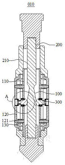
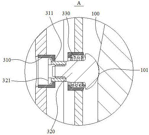
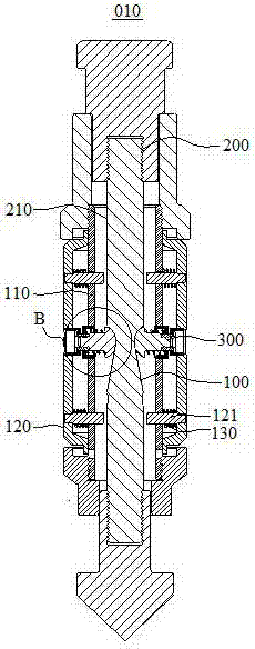
[0058] Please refer to Figure 1-Figure 4 . figure 1 A schematic structural diagram of the fluid separation device 010 in an expanded state provided for this embodiment. figure 2 for figure 1 Enlarged view of A. image 3 A schematic structural diagram of the fluid separation device 010 in a contracted state provided for this embodiment. Figure 4 for image 3 Enlarged view of B.

[0059] In this embodiment, the fluid separation device 010 includes a cylinder 110 , a partition 120 , a first elastic member 130 , a first guiding device 200 and a second guiding device 300 . A plurality of partitions 120 are arranged around the barrel 110 . The first elastic member 130 is disposed between the separator 120 and the cylinder body 110 , and the first elastic member 130 exerts a radially outward elastic force on the separator 120 so that the first separator 120 can radially rotate relative to the cylinder body 110 . outside sports. The first guide device 200 is axially threade...

Embodiment 2

[0068] Please refer to Figure 7-Figure 10 . Figure 7 A schematic structural diagram of the fluid separation device 010 in an expanded state provided for this embodiment. Figure 8 for Figure 7 Enlarged view of C. Figure 9 A schematic structural diagram of the fluid separation device 010 in a contracted state provided for this embodiment. Figure 10 for Figure 9 Enlarged view of D.

[0069] In this embodiment, the fluid separation device 010 includes a cylinder 110 , a partition 120 , a first elastic member 130 , a first guiding device 200 and a second guiding device 300 . A plurality of partitions 120 are arranged around the barrel 110 . The first elastic member 130 is disposed between the separator 120 and the cylinder body 110 , and the first elastic member 130 exerts a radially outward elastic force on the separator 120 so that the first separator 120 can radially rotate relative to the cylinder body 110 . outside sports. The first guide device 200 is axially t...

Embodiment 3

[0077] Please refer to Figure 13-Figure 16 . Figure 13 A schematic structural diagram of the fluid separation device 010 in an expanded state provided for this embodiment. Figure 14 for Figure 13 Enlarged view of E. Figure 15 A schematic structural diagram of the fluid separation device 010 in a contracted state provided for this embodiment. Figure 16 for Figure 15 Enlarged view of F.

[0078] In this embodiment, the fluid separation device 010 includes a cylinder 110 , a partition 120 , a first elastic member 130 , a first guiding device 200 and a second guiding device 300 . A plurality of partitions 120 are arranged around the barrel 110 . The first elastic member 130 is disposed between the separator 120 and the cylinder body 110 , and the first elastic member 130 exerts a radially outward elastic force on the separator 120 so that the first separator 120 can radially rotate relative to the cylinder body 110 . outside sports. The first guide device 200 is axi...


PUM


Abstract

The invention relates to the technical field of oil and gas exploitation, and discloses a fluid separating device, a shaft structure and a method for producing petroleum or natural gas. The fluid separating device comprises a barrel, a plurality of separators, a first elastic component, a first guide device and a second guide device. The separators are arranged around the barrel; the first elastic component is arranged between the separators and the barrel, and elastic force can be outwardly applied to the separators by the first elastic component along the radial direction of the barrel; the first guide device axially penetrates the barrel and is structured in such a manner that the first guide device can move back and forth between an expansion location and a contraction location along the axial direction of the barrel; the second guide device penetrates the barrel, one end of the second guide device is connected with the separators, and the other end of the second guide device is slidably matched with the first guide device by a matched surface. The fluid separating device, the shaft structure and the method have the advantages that frictional force between the separators and the inner wall of a shaft be eliminated when the fluid separating device descends, and the fluid separating device further can quickly descend to return shaft bottoms.

Description

technical field [0001] The invention relates to the technical field of oil and gas exploitation, in particular to a fluid separation device, a shaft structure and a method for producing oil or natural gas. Background technique [0002] During the development of oil and gas wells, when the oil or natural gas production in the well is low and the pressure in the well is insufficient, a large amount of liquid cannot be lifted to the surface, which will form a certain degree of liquid accumulation at the bottom of the well, which will reduce the production capacity of the oil and gas well, and even cause oil and gas The well stopped blowing. [0003] A related art known to the inventor provides a fluid separation device. A plurality of partitions are arranged on the periphery of the fluid partition device, and these partitions are always in contact with the inner wall of the hoistway under the action of the elastic member to form a seal. In this way, the pressure generated by ...

Claims


Application Information

Patent Timeline
Patent Type & Authority Applications(China)
IPC IPC(8): E21B33/12
CPCE21B33/1208E21B43/38
Inventor 陈俊宏唐勇张罡李军民刘瀚森张忠林刘树飞苏诗策易诚雄周华谭宇茜唐湉刘向美珂周侗侗刘士吉
Owner CHENGDU BISON TECH CO LTD
Why Eureka
Try Eureka