
Electromagnetically-driven fan device

An electromagnetic drive and fan technology, applied in the direction of the pump device, the air inlet of the turbine/propulsion device, the charging system, etc., to achieve the effects of improving fan efficiency and overall machine efficiency, increasing the thrust-to-weight ratio, and reducing the weight of the fan

Inactive Publication Date: 2017-11-03
李小顺
View PDF0 Cites 1 Cited by
  • Summary
  • Abstract
  • Description
  • Claims
  • Application Information

AI Technical Summary

Problems solved by technology

[0006] Based on the technology of multi-electric aircraft and multi-electric engine, it is necessary to develop a new type of fan device and system that adopts electromagnetic drive mode. At present, there is no relevant report on this kind of electromagnetically driven engine fan or compressor. It has technical advantages. novelty and feasibility

Method used


Image

  • Electromagnetically-driven fan device
  • Electromagnetically-driven fan device

Examples


Embodiment Construction

[0013] The present invention will be described in further detail below in conjunction with the accompanying drawings and specific embodiments.

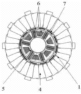
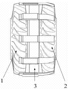
[0014] Such as figure 1 , figure 2 As shown, an embodiment of the present invention includes a first-stage fan rotor 1 , a second-stage fan rotor 2 , a fan stator 3 , a fan blade 4 , a coil winding 6 , and a disc 7 . The first-stage fan rotor 1 and the second-stage fan rotor 2 constitute the low-pressure compressor system of the aero-engine, which are symmetrically located on both sides of the first-stage fan stator 3, and respectively include a plurality of fan blades 4 fixed on the circumference of the disc 7 . A ring-shaped integral permanent magnet is embedded on the disc 7 to generate a symmetrical four-level magnetic flux. The coil winding 6 is located inside the permanent magnet. When the current passes through the coil winding 6, the current interacts with the magnetic field of the permanent magnet to generate radial levit...


PUM


Abstract

The present invention provides an electromagnetically driven fan device, which includes: a disc, a fan rotor, a fan stator, and a coil winding; the disc is embedded with a circular permanent magnet to generate a symmetrical four-level magnetic flux. The fan rotor includes a plurality of fan blades, and the fan blades are fixed to the disc; the coil winding is located inside the permanent magnet and fixed on the fan stator, so as to serve as a connection between the stator and the permanent magnet when energized. The interaction of the magnetic fields generates a radial levitation force to realize the radial stable levitation of the fan rotor; meanwhile, based on the excitation principle of the permanent magnet brushless DC motor, the fan rotor is driven to rotate by means of electric excitation. The electromagnetically driven fan device provided by the present invention can realize the electromagnetization and shaftless driving of the fan rotor, improve the stability and controllable margin of the fan, greatly reduce the weight of the fan, thereby improving the efficiency of the fan of the aeroengine and the efficiency of the whole machine, and reducing the weight of the engine. weight and improved thrust-to-weight ratio.

Description

technical field [0001] The present invention relates to the technical field of electromagnetic drive, in particular, the present invention particularly relates to an electromagnetic drive fan device. Background technique [0002] In the future, advanced aero-engines will develop toward multi-electric or all-electric technology. Countries such as the United States, Britain, and France have launched research programs on multi-electric engines, which are expected to be practically applied between 2015 and 2020. In the IHPTET plan formulated by the United States in 1988, it was first proposed to study multi-electric or all-electric aeroengines supported by magnetic suspension bearings, and developed a high-temperature magnetic suspension bearing system that meets the requirements of the sky during the 10-year progress. This technology has become one of the key high technologies of advanced aero-engines in the 21st century. [0003] The so-called magnetic levitation multi-electr...

Claims


Application Information

Patent Timeline
IPC IPC(8): F04D25/02F04D25/08F02C7/04
CPCF04D25/026F02C7/04F04D25/08
Inventor 李小顺
Owner 李小顺
Learn More