Self-lubricating rolling bearing

A rolling bearing and self-lubricating technology, applied in the field of bearings, can solve the problems of reduced service life of bearings, increased wear of bearing outer rings and rolling elements

Pending Publication Date: 2017-11-03
徐州博丰轴承有限公司
View PDF14 Cites 0 Cited by
  • Summary
  • Abstract
  • Description
  • Claims
  • Application Information

AI Technical Summary

Problems solved by technology

However, in the prior art, for the installation method in which the inner ring of the bearing is fixed and the outer ring rotates, the outer ring of the bearing rotates out of the lubricating oil in the oil groove and quickly flows back into the oil groove, causing the outer ring of the bearing to be in an environment with insufficient lubrication. It is easy to aggravate the wear of the bearing outer ring and rolling elements, reducing the service life of the bearing

Method used


Image

  • Self-lubricating rolling bearing
  • Self-lubricating rolling bearing
  • Self-lubricating rolling bearing

Examples


Embodiment Construction

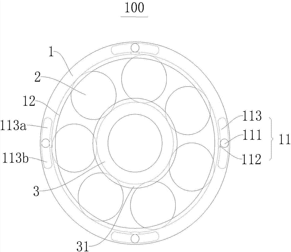
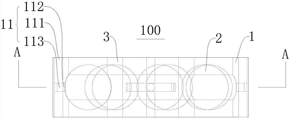
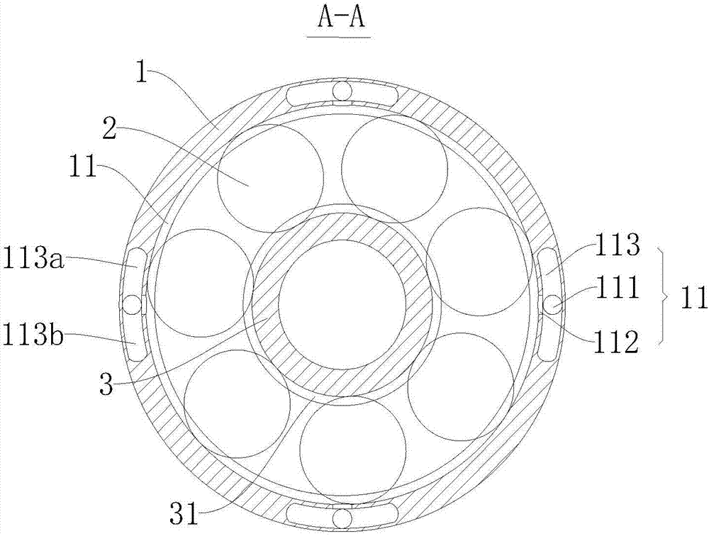
[0024] Refer to the following as Figure 1 ~ Figure 3 The illustrated self-lubricating rolling bearing 100 according to the embodiment of the present invention is described in detail. Such as Figure 1 ~ Figure 3 As shown, the self-lubricating rolling bearing 100 according to the embodiment of the present invention includes: a bearing outer ring 1 , rolling elements 2 , a bearing inner ring 3 and a hole assembly 11 .

[0025] Bearing outer ring 1, rolling body 2, bearing inner ring 3, bearing inner ring 3 is arranged in bearing outer ring 1, rolling body 2 is arranged between bearing inner ring 3 and bearing outer ring 1, bearing inner ring 3 and bearing outer ring There are raceways on the ring 1, that is, the first raceway 12 is provided on the bearing outer ring 1, the second raceway 31 is provided on the bearing inner ring 3, and the rolling elements 2 are located between the first raceway 12 and the second raceway. 31; that is to say, the relative rotational motion betw...


PUM


Abstract

The invention discloses a self-lubricating rolling bearing. The self-lubricating rolling bearing comprises a bearing inner ring (3), a bearing outer ring (1) and a rolling body (2); the bearing inner ring (3) is arranged in the bearing outer ring (1); the rolling body (2) is arranged between the bearing inner ring (3) and the bearing outer ring (1); a hole assembly (11) comprises a guide hole (111) and a through hole (112); the guide hole (111) is formed in the side wall of the bearing outer ring (1); the through hole (112) is formed along the radial direction of the bearing outer ring (1); and the through hole (112) is connected with the area of the guide hole (111), the bearing inner ring (3) and the bearing outer ring (1). The self-lubricating rolling bearing can prolong the lubricating time and enhance the flowability of lubricating oil so as to prolong the service life of a bearing.

Description

technical field [0001] The invention relates to the technical field of bearings, in particular to a self-lubricating rolling bearing. Background technique [0002] Oil bath lubrication is the most common lubrication method for rolling bearings. It is suitable for the lubrication of low-speed bearings. During the lubrication process of rolling bearings, the bearing part is soaked in the lubricating oil in the oil tank. The lubricating oil is carried by the rotating bearing parts and then flows back into the oil tank. . However, in the prior art, for the installation method in which the inner ring of the bearing is fixed and the outer ring rotates, the outer ring of the bearing rotates out of the lubricating oil in the oil groove and quickly flows back into the oil groove, causing the outer ring of the bearing to be in an environment with insufficient lubrication. It is easy to aggravate the wear of the outer ring of the bearing and the rolling elements, reducing the service ...

Claims


Application Information

Patent Timeline
IPC IPC(8): F16C19/16F16C33/58F16C33/66F16C33/38
CPCF16C19/16F16C33/38F16C33/583F16C33/6659
Inventor 程波彭超
Owner 徐州博丰轴承有限公司
Why Eureka
Try Eureka