

Filtering tank
A filter tank and orifice plate technology, applied in the field of filter tank, can solve the problems of filter material leakage, easy breakage, poor filtering effect, etc.
Inactive Publication Date: 2017-11-07
江阴宇博科技有限公司
View PDF0 Cites 0 Cited by
- Summary
- Abstract
- Description
- Claims
- Application Information
AI Technical Summary
Problems solved by technology
[0002] The currently commonly used filter tank includes a tank body with an inner cavity, and a wire mesh that is arranged in the inner cavity and is fixedly connected with the tank body around it. The wire mesh structure has poor rigidity and is easily broken. tearing, and the tightness between the screens or between the screen and the tank body is poor, which may easily cause leakage of the filter material and poor filtering effect
Method used
View moreImage
Smart ImageViewing Examples

Examples
Embodiment 1
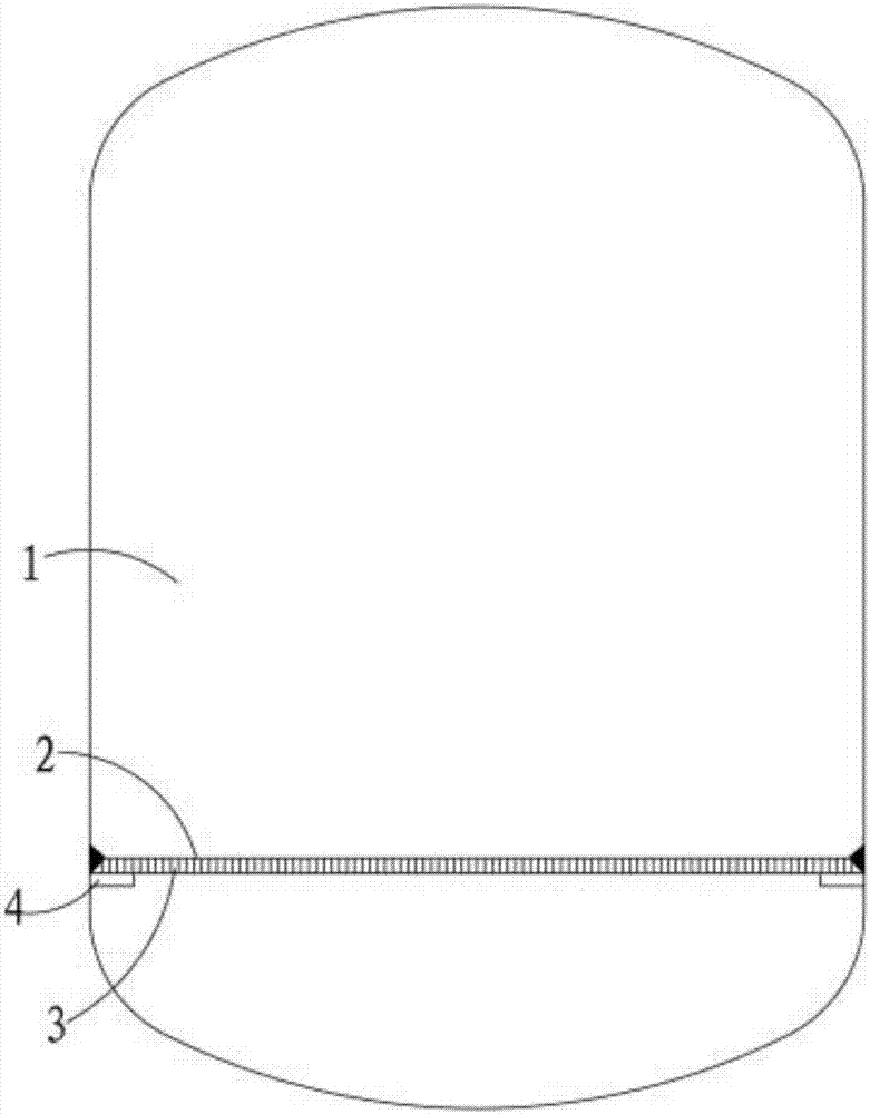
[0012] see figure 1 As shown, a filter tank includes a tank body 1 with an inner cavity and an orifice 2 fixedly connected with the tank body 1. The orifice 2 is arranged in the inner cavity, and the orifice 2 is provided with a plurality of through holes 3. The corresponding two sides of the inner wall of the tank body 1 are fixedly provided with a support frame 4, and the two ends of the orifice plate 2 are erected on the support frame 4 on the corresponding side and fixed, and a circular hole is used in the tank body 1 of the filter tank. The perforated plate 2 has an opening rate higher than 90%, and the circular holes are irregularly distributed, wherein the thickness of the orifice plate 2 is preferably 1.5mm.
Login to View More PUM
| Property | Measurement | Unit |
|---|---|---|
| Thickness | aaaaa | aaaaa |
Abstract
The invention provides a filter tank, which includes a tank body with an inner cavity and an orifice plate fixedly connected with the tank body. The orifice plate is arranged in the inner cavity, and a plurality of through holes are opened on the orifice plate. Both sides of the filter tank are fixedly provided with a support frame, and the two ends of the orifice plate are respectively erected on the support frame on the corresponding side and fixed. A porous plate with circular holes is used in the tank body of the filter tank, and the opening rate is higher than 90% %, and the circular holes are irregularly distributed. The purpose of the present invention is to overcome the defects in the prior art, and provide a filter tank with simple and reasonable structure, good rigidity and good performance of leakage.
Description
technical field [0001] The invention relates to a filter tank. Background technique [0002] The currently commonly used filter tank includes a tank body with an inner cavity, and a wire mesh that is arranged in the inner cavity and is fixedly connected with the tank body around it. The wire mesh structure has poor rigidity and is easily broken. Tearing, and poor sealing between the screens or between the screen and the tank body, it is easy to cause leakage of the filter material, and the filtering effect is poor. Contents of the invention [0003] The invention provides a filter tank, which solves the defects in the prior art. [0004] In order to achieve the above object, the present invention proposes a filter tank, including a tank body with an inner cavity and an orifice plate fixedly connected with the tank body, the orifice plate is arranged in the inner cavity, and the A plurality of through holes are opened on the orifice plate, support frames are fixedly arran...
Claims
Login to View More Application Information
Patent Timeline
 IPC IPC(8): B01D35/30
CPCB01D35/30
Inventor 陈伟刚金龙华夏杜威
Owner 江阴宇博科技有限公司