
Automobile wire harness pay-off rack
A technology of automobile wire and pay-off frame, which is applied in the direction of conveying filamentous materials, thin material processing, transportation and packaging, etc., and can solve problems such as knotting in the pay-off process, low pay-off efficiency, and entanglement
Patent Information
- Authority / Receiving Office
- CN · China
- Current Assignee / Owner
- Publication Date
- 2017-11-07
- Estimated Expiration
- Not applicable · inactive patent
Smart Images
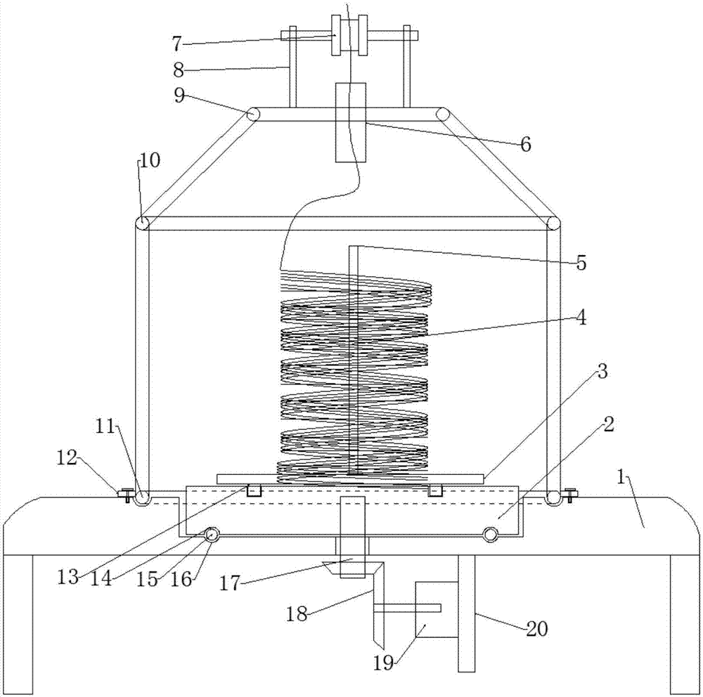
Figure 1 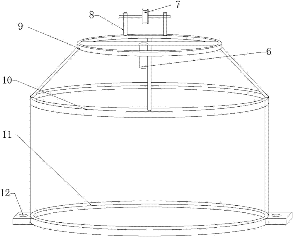
Figure 2
Abstract
Description
technical field
[0001] The invention relates to the field of electrical connectors, in particular to an automobile wiring harness pay-off rack. Background technique:
[0002] With the improvement of people's requirements on automobile power performance, economic performance, emission performance and ride comfort performance, as well as the rapid development of electronic industry and computer technology, more and more electrical equipment are equipped on automobiles. As the carrier of automotive circuit and electrical equipment signal transmission, automotive wiring harness plays a vital role in ensuring the normal driving of the car and the stability of various performances. Therefore, the production of automotive wiring harness is one of the key control processes in the quality management system of automobile manufacturing enterprises. one.
[0003] In the prior art, there is no special device for paying off wires, but the wire harness is directly placed on an ordinary pa...
Examples
Embodiment Construction
[0014] In order to make the technical means, creative features, goals and effects achieved by the present invention easy to understand, the present invention will be further described below in conjunction with specific embodiments.
[0015] Such as figure 1 and figure 2 As shown, a wire harness pay-off stand for automobiles includes a support platform 1 and a pay-off stand. The support platform 1 is provided with a disc-shaped groove, and a rotating disk 2 is installed in the groove. The lower end surface of the disc 2 is provided with an upper annular groove 14, and the bottom of the groove is provided with a lower annular groove 16 opposite to the upper annular groove 14, and a roller is installed between the upper annular groove 14 and the lower annular groove 16. 15, the central position of the groove is provided with a through hole, the lower end of the support table 1 is equipped with a rotating motor 19 through a fastening plate 20, and the driving end of the rotating...