A head-mounted display device based on holographic waveguide

A head-mounted display, holographic waveguide technology, applied in instruments, optical components, optics, etc., can solve the problems of separation of the field of view, split of the field of view, discontinuous exit pupil, etc. Effects of Field Splitting Phenomenon

Active Publication Date: 2019-04-30
SOUTHEAST UNIV
View PDF5 Cites 0 Cited by
  • Summary
  • Abstract
  • Description
  • Claims
  • Application Information

AI Technical Summary

Problems solved by technology

[0004] However, for the existing holographic waveguide system, there are discontinuous exit pupils and separation of field of view
Although the existing technology tries to make the exit pupil continuous and uniform through the two-dimensional exit pupil expansion method, most of the designs in the prior art only aim at the uniform expansion of the exit pupil at a specific field of view (generally the central field of view), so that in the Severe field of view splitting occurs when the field of view angle is large

Method used


Image

  • A head-mounted display device based on holographic waveguide
  • A head-mounted display device based on holographic waveguide
  • A head-mounted display device based on holographic waveguide

Examples


Embodiment 2

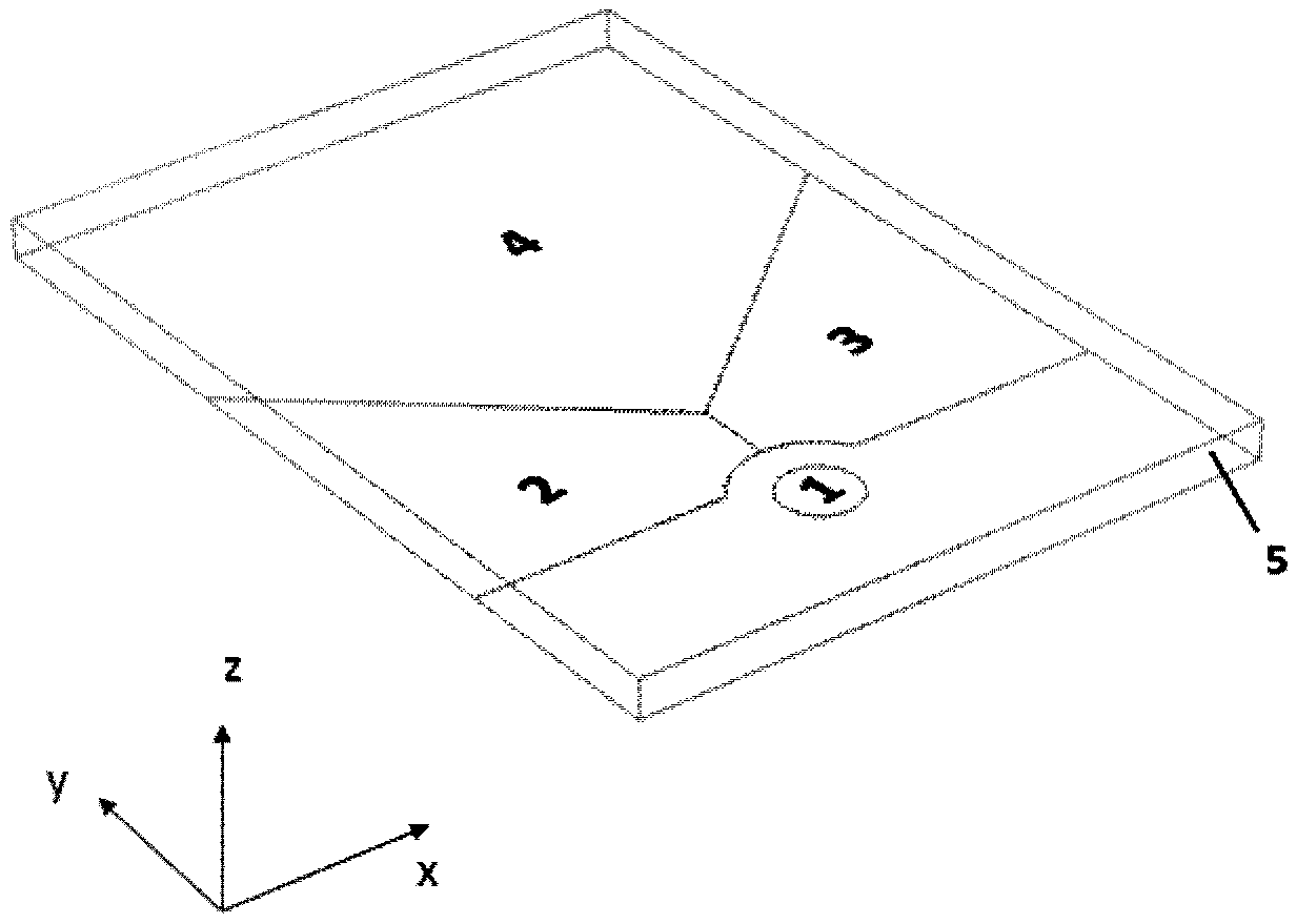
[0039] Embodiment 2, as a preference, the entrance pupil coupling grating 1 containing two grating components can be a double-layer volume holographic grating, or it can be prepared by exposing the same holographic material twice.

[0040] In a specific implementation, the shape of the in-coupling grating can be circular, rectangular, or other shapes, which should be determined by the shape of the entrance pupil optical system. Its size is generally less than 20mm.

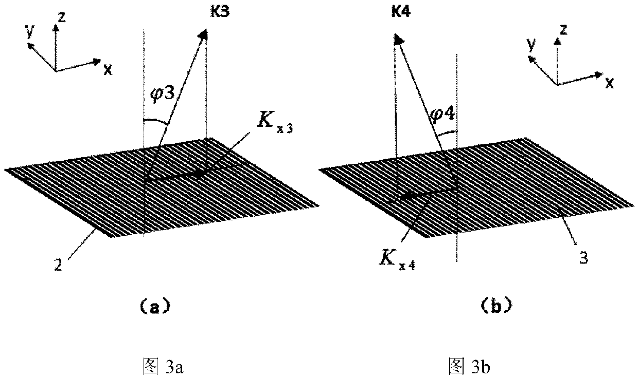
[0041] As shown in FIG. 3 , the grating vectors of the deflection grating 2 in the left field of view and the deflection grating 3 in the right field of view are coplanar on the plane xz, and at the same time, are mirror-symmetrical to the plane yz. Therefore, the deflection grating 2 in the left field of view and the deflection grating 3 in the right field of view only have the grating component K in the x direction in the xy plane x2 and Kx3 . At the same time, it corresponds to the grating vector in the x dir...


PUM


Abstract

The invention discloses a head-mounted display device based on a holographic waveguide, which comprises an in-coupling grating (1), a deflection grating in the left field of view (2), a deflection grating in the right field of view (3), and an out-coupling grating ( 4), rectangular waveguide (5); in-coupling grating (1), left-field deflection grating (2), right-field deflection grating (3), out-coupling grating (4), attached to the rectangular waveguide (5 ) on the upper or lower surface; the in-coupling grating (1), the left-field deflection grating (2), the right-field deflection grating (3), the out-coupling grating (4), and the rectangular waveguide (5) are pasted on The surface or subsurface is determined by the design direction of the entrance and exit pupil rays. The invention uses the pupil reshaping method to solve the separation of the field of view in the case of a large field of view angle produced by the traditional two-dimensional pupil expansion method.

Description

technical field [0001] The invention relates to a head-mounted display device, which uses a waveguide system to transmit images in front of the wearer's eyes to realize the application of augmented reality. Background technique [0002] With the development of technology, display devices are widely used on various carriers. As an off-axis optical system, the waveguide system can realize the application of transmissive display, that is, the application of augmented reality by projecting a specific image frame in front of the viewer without blocking the external light environment. At the same time, compared with the traditional imaging method, the waveguide display method, because the light is folded and propagated in the waveguide, can be coupled and exported at different positions in the waveguide, so it is not limited by the Lagrangian optical infinity, and can achieve uniformity in a certain field of view. Pupil dilation output. Waveguide display systems typically utiliz...

Claims


Application Information

Patent Timeline
Patent Type & Authority Patents(China)
IPC IPC(8): G02B27/01
CPCG02B27/0172G02B2027/011G02B27/4272G02B2027/0174
Inventor 张宇宁翁一士刘奡沈忠文李晓华
Owner SOUTHEAST UNIV
Why Eureka
Try Eureka