Semi-automatic solar module border remover

A technology for solar modules and dismantling machines, which is applied in metal processing, metal processing equipment, manufacturing tools, etc., can solve the problems of high work intensity of employees and damage to battery sheets, so as to reduce labor costs, improve work efficiency, and protect solar cells board effect

Pending Publication Date: 2017-11-10
成都中浦科技有限公司
View PDF10 Cites 3 Cited by
  • Summary
  • Abstract
  • Description
  • Claims
  • Application Information

AI Technical Summary

Problems solved by technology

[0005] The invention provides a semi-automatic solar module frame removal machine, which is used to solve the technical problems existing in the prior art: during the disassembly process of the aluminum frame, the cells in the solar photovoltaic module are easily damaged, and the work intensity of the employees is high.

Method used


Image

  • Semi-automatic solar module border remover
  • Semi-automatic solar module border remover
  • Semi-automatic solar module border remover

Examples


Embodiment 1

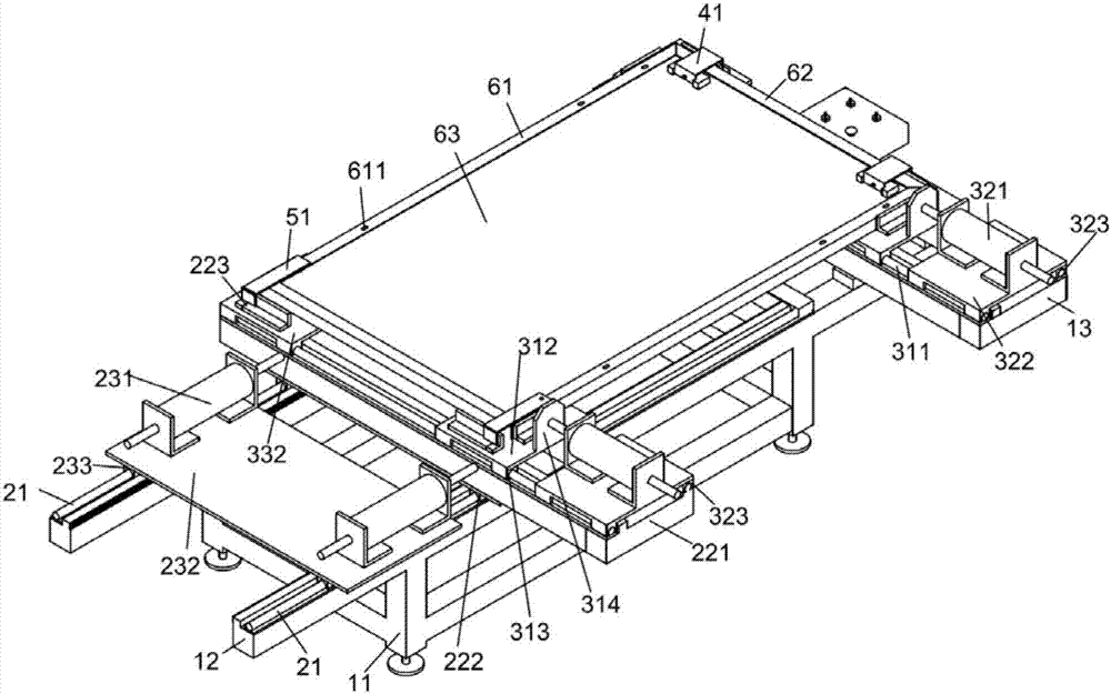
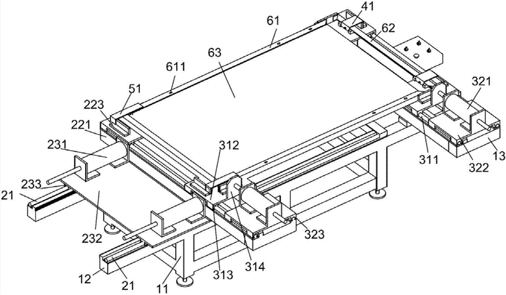
[0031] A semi-automatic solar module frame removal machine, such as Figure 1~5 As shown, it includes two fixing frames 12, and the two fixing frames 12 are sequentially provided with a fixing plate 13, a component placement platform and a longitudinal sliding device, and a solar module is placed on the module placement platform, and the solar module includes solar energy The battery panel 63 and the short frame 62 and the long frame 61 that cover the four sides of the solar cell panel 63, the fixing plate 13 is provided with a clamp 41 that can be clamped at the corner of the short frame 62 and a longitudinal baffle 223 that can position the solar module ;

[0032] The longitudinal sliding device includes a longitudinal sliding bar 21 arranged above the fixed frame 12, and the longitudinal sliding bar 21 is provided with a longitudinal sliding mechanism capable of longitudinally sliding, and the longitudinal sliding mechanism includes a vertical sliding mechanism arranged on ...

specific Embodiment approach

[0038] The first step: place the solar module on the module placement table;

[0039] Step 2: Clamp the fixture 41 on the short frame 62 of the solar module, and at the same time clamp the fixture 41 on the longitudinal baffle 223 to make it stable, as figure 1 or figure 2 shown;

[0040] The third step: embed the puller tool 51 on the long frame 61 of the solar module, and at the same time, the puller tool 51 also clamps the longitudinal baffle 223 to make it stable, such as figure 1 or figure 2 shown;

[0041] Step 3: activate the longitudinal cylinder 231, slide the longitudinal cylinder 231 outward, remove a short frame 62, and return the cylinder to its original position;

[0042] Step 4: Reverse the solar module, and repeat the installation of clamp 41 and puller 51;

[0043] Step 5: start the longitudinal cylinder 231, slide the longitudinal cylinder 231 outside, remove the other short frame 62, and return the cylinder to its original position;

[0044] Step 6: ...

Embodiment 2

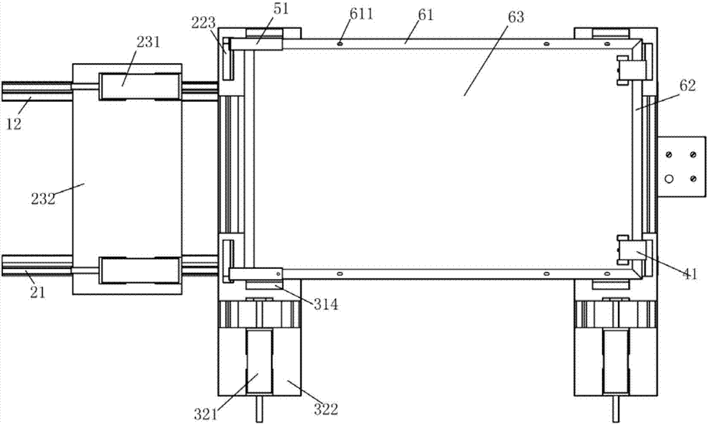
[0047] This embodiment is further optimized on the basis of the above embodiments, such as Figure 1~5 As shown, the longitudinal sliding plate 221 and the fixed plate 13 are provided with a horizontal baffle 314 capable of positioning solar modules; the bottom of the longitudinal sliding plate 221 is provided with a longitudinal sliding groove a222 matching the longitudinal sliding bar 21; The longitudinal transmission mechanism also includes a longitudinal installation plate 232 for installing the longitudinal cylinder 231 , and the bottom of the longitudinal installation plate 232 is provided with a longitudinal sliding groove b233 capable of matching with the longitudinal sliding rod 21 .

[0048] The specific implementation mode of increasing the above-mentioned technical features: in order to make the lateral positioning of the device more accurate during the dismantling process, a lateral baffle 314 is adopted, and the fixed plate 13 and the longitudinal sliding plate 22...


PUM


Abstract

The invention discloses a semi-automatic module border remover. The remover comprises two fixed frames, fixed plates, a module containing table and a longitudinal sliding device are arranged on the two fixed frames in sequence, a solar module is arranged on the module containing table and comprises a solar panel, short borders and long borders, the short borders and long borders wrap the four edges of the solar panel, fixtures capable of being clamped at the corners of the short borders and longitudinal baffles capable of positioning the solar module are arranged on the fixed plates, the longitudinal sliding device comprises longitudinal sliding rods arranged above the fixed frames, each longitudinal sliding rod is provided with a longitudinal sliding mechanism capable of sliding in the longitudinal direction, each longitudinal sliding mechanism comprises a longitudinal sliding plate arranged on the corresponding longitudinal sliding rod, and each longitudinal sliding plate is provided with a Rama tool capable of being connected with the corresponding long border; the longitudinal sliding device further comprises longitudinal transmission mechanisms providing power for the longitudinal sliding mechanisms, and each longitudinal transmission mechanism comprises a longitudinal cylinder which is connected with the corresponding longitudinal sliding plate.

Description

technical field [0001] The invention relates to the technical field of solar photovoltaic module frame, specifically, a semi-automatic solar module frame removal machine. Background technique [0002] The solar photovoltaic module is the core part of the solar power generation system, and it is also the most important part of the solar power generation system. During the framing process of the solar photovoltaic module, aluminum frames are often installed on the solar photovoltaic module to increase the strength of the solar photovoltaic module, and further Protect solar photovoltaic modules and prolong the service life of batteries inside solar photovoltaic modules. At present, the aluminum frames of conventional solar photovoltaic modules are connected by corner codes. However, in the process of encapsulating the aluminum frame of the solar photovoltaic module, aluminum frame defects often occur, resulting in unqualified product quality. In order to solve the defects and ...

Claims


Application Information

Patent Timeline
Patent Type & Authority Applications(China)
IPC IPC(8): B23P19/00
CPCB23P19/00
Inventor 孙曾平
Owner 成都中浦科技有限公司
Why Eureka
Try Eureka