
Automatic screwdriving machine

A screw locking machine and automatic technology, which is applied in metal processing, metal processing equipment, manufacturing tools, etc., can solve the problems of skewed locking screws, failure to lock to the bottom, and inability to automatically lock, etc., so as to improve stability and accuracy , Overcome the effect of not being able to automatically lock the payment

Pending Publication Date: 2017-11-10
东莞市富勤自动化设备有限公司
View PDF5 Cites 11 Cited by
  • Summary
  • Abstract
  • Description
  • Claims
  • Application Information

AI Technical Summary

Problems solved by technology

[0004] There are many existing screw locking machines, and there are many types of screws. The cross slot, plus and minus slot, slot, and Pozi slot can use the blowing type automatic locking screw machine, and the inner hexagon can use the suction type automatic locking screw. machine, but some screws with special specifications such as two-point slots, one-point slots, three-point slots, triangular slots, and herringbone slots cannot be automatically locked by screw lock machines on the market, and the screw locks currently on the market The paid machine often has the disadvantage that the lock screw is skewed and cannot be locked to the bottom

Method used


Image

  • Automatic screwdriving machine
  • Automatic screwdriving machine
  • Automatic screwdriving machine

Examples


Embodiment Construction

[0017] The following will clearly and completely describe the technical solutions in the embodiments of the present invention with reference to the accompanying drawings in the embodiments of the present invention. Obviously, the described embodiments are only some, not all, embodiments of the present invention. Based on the embodiments of the present invention, all other embodiments obtained by persons of ordinary skill in the art without making creative efforts belong to the protection scope of the present invention.

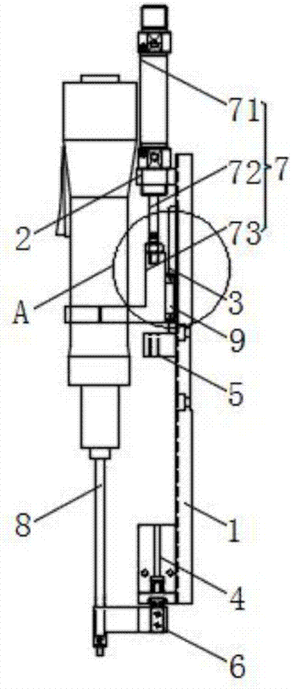
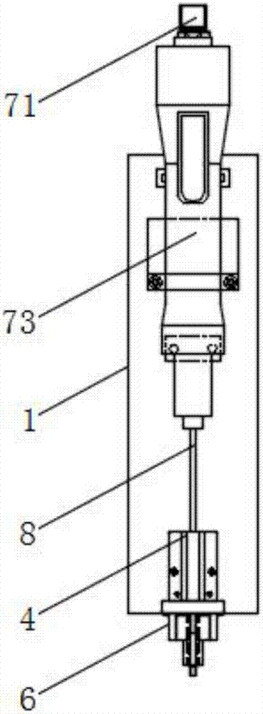
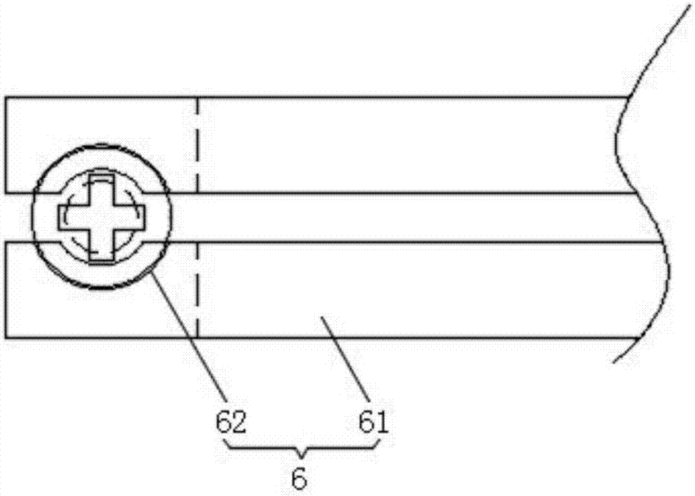
[0018] see figure 1 , figure 2 and Figure 4 , the present invention provides a technical solution: an automatic screw locking machine, including a fixed chassis 1 and a fixing device 2, one side of the outer surface of the fixed chassis is sequentially provided with a fixing device, a slide rail 3 and a clip Picking device 4, stroke sensing blocks 5 are symmetrically arranged on the left and right outer walls of the slide rail, and the clamping profiling p...


PUM


Abstract

The invention discloses an automatic screwdriving machine which comprises a fixing bottom frame and a fixing device. The fixing device, a slide rail and a clamping device are arranged on the outer surface of one side of the fixing bottom frame from top to bottom in sequence. Travel induction blocks are arranged symmetrically on the left outer side wall and the right outer side wall of the slide rail correspondingly. The clamping device is fixedly connected with a clamping profile part. A lifting driving device is arranged in the fixing device and comprises a drive air cylinder. The power output end of the drive air cylinder is provided with one end of a lifting rod. An electric screwdriver fixing clamp is arranged at the other end of the lifting rod. An electric screwdriver is arranged in the electric screwdriver fixing clamp. According to the automatic screwdriving machine provided by the invention, the shortcomings that an electric screwdriver head of a screwdriving machine available on the present market fails enter a screw groove, and consequentially screw is driven obliquely and not driven in place are overcome, and meanwhile, the problem that screws of special specifications fail to be driven automatically can be solved; and in addition, the automatic screwdriving machine provided by the invention is compact in overall structure, small in size, easy to produce and manufacture, low in cost and capable of facilitating application and popularization widely.

Description

technical field [0001] The invention relates to the technical field of automatic screw locking, and the specific field is an automatic screw locking machine. Background technique [0002] With the development of industrial modernization, more and more products require screw locks, and screw lock machines are indispensable components in production. [0003] Most products need to be driven with more or less screws, and the traditional hand-tightening method is generally used when assembling the screws on the products, which wastes a lot of manpower and material resources, and the work efficiency is low. Later, with the rapid development of science and technology, locking tools such as electric screwdrivers and pneumatic screwdrivers gradually appeared, replacing the manual tightening method, improving work efficiency and reducing the work intensity of workers locking screws. [0004] There are many existing screw locking machines, and there are many types of screws. The cross...

Claims


Application Information

Patent Timeline
Patent Type & Authority Applications(China)
IPC IPC(8): B23P19/06
CPCB23P19/06
Inventor 鲍士英
Owner 东莞市富勤自动化设备有限公司
Learn More