Boost flow centrifugal fan

A centrifugal fan and booster technology, which is applied in mechanical equipment, machines/engines, liquid fuel engines, etc., can solve the problems of insignificant effect and non-soot gas diversion, etc., so as to improve the suction efficiency, improve the flow field, and improve the The effect of suction and discharge

Pending Publication Date: 2017-11-10
NINGBO FOTILE KITCHEN WARE CO LTD
View PDF11 Cites 0 Cited by
  • Summary
  • Abstract
  • Description
  • Claims
  • Application Information

AI Technical Summary

Problems solved by technology

In this way, when the air flow passes through the air inlet, the rectification effect of the rectification net is used to avoid turbulent flow when the flue gas enters the air inlet; obvious
[0004] Another example is CN201110432232.0 which discloses a "Multi-blade Centrifugal Fan with Multifunctional Flow Guidance Device", in which guide blades and flow guides

Method used


Image

  • Boost flow centrifugal fan
  • Boost flow centrifugal fan
  • Boost flow centrifugal fan

Examples


Embodiment Construction

[0027] The present invention will be further described in detail below in conjunction with the accompanying drawings and embodiments.

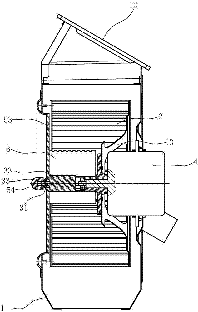
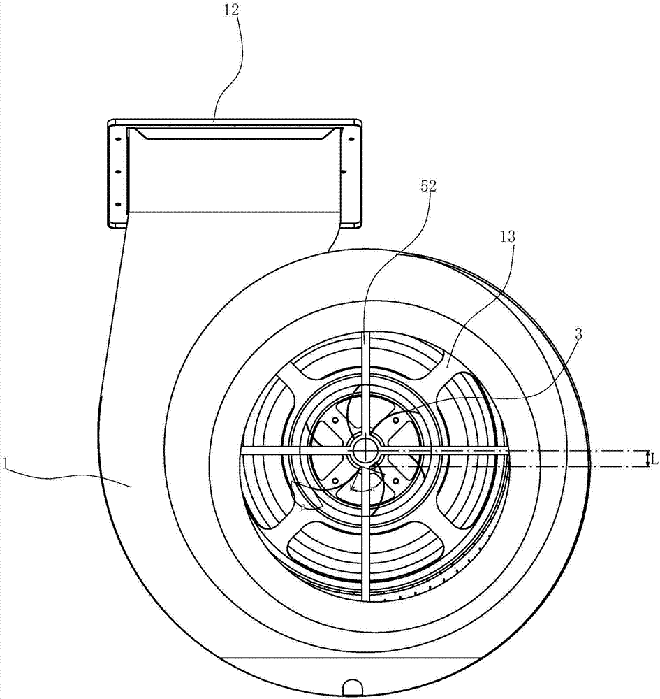
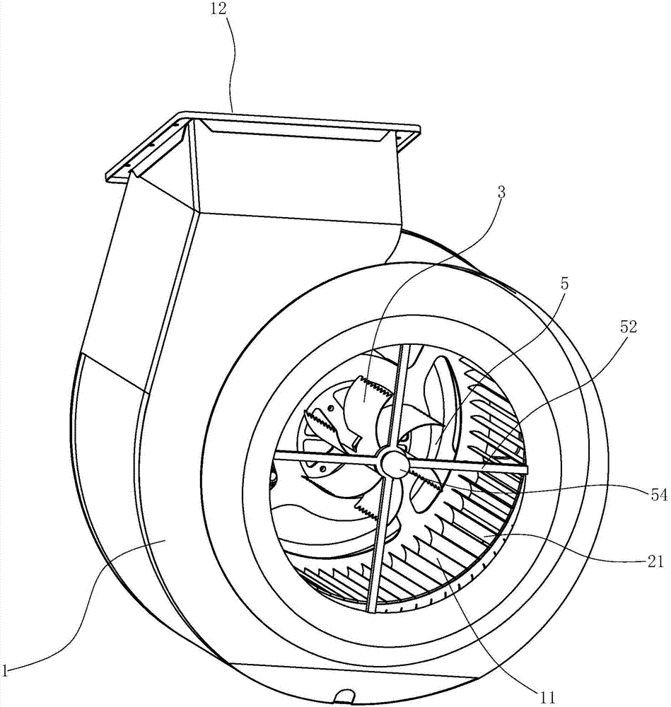
[0028] like Figure 1 to Figure 6 As shown, the multi-blade centrifugal fan includes:

[0029] The volute 1 , the impeller 2 arranged in the volute 1 and the motor 4 driving the impeller 2 to rotate, the volute 1 is provided with an air inlet 11 and an air outlet 12 . The motor 4 is located in the middle of the impeller 2 , and the output shaft of the motor 4 is connected to the impeller 2 through the central plate 13 .

[0030] In the present embodiment, the outer edge of each blade 21 of the impeller 2 is wavy, as Image 6 to improve the noise reduction effect.

[0031] The guide vanes 3 are located on the inner side of the impeller 2 and face the air inlet 11 of the volute 1. There are several pieces, six pieces in this embodiment, which are arc-shaped. On the outer surface, and arranged helically along the periphery of the rotating sha...


PUM

PropertyMeasurementUnit
Maximum widthaaaaaaaaaa

Abstract

The invention relates to a boost flow centrifugal fan. The boost flow centrifugal fan comprises a volute (1), an impeller (2) arranged in the volute (1), and a motor (4) arranged in the volute (1) for driving the impeller (2) to rotate; and the volute (1) is provided with an intake port (11) and an exhaust port (12). The boost flow centrifugal fan is characterized in that at least two guide blades (3) are eccentrically arranged on the inner side of the impeller (2) in the volute (1); the guide blades (3) are connected with a bearing (31), and are uniformly distributed at the peripheral edge of the bearing (31); multiple air holes (32) are formed in the surfaces of the guide blades (3) at intervals; the bearing (31) is eccentrically arranged corresponding to the center of the impeller (2), and is connected to a bracket (5); and the bracket (5) is connected to the volute (1).

Description

technical field [0001] The invention relates to a centrifugal fan, in particular to a centrifugal fan with booster flow. Background technique [0002] Most of the fans used in range hoods are multi-blade centrifugal fans. The air flow field at the impeller inlet of the centrifugal fan will produce turbulent flow, swirl and other turbulent air fields, which will reduce the air volume, wind pressure and total pressure efficiency of the fan. [0003] CN201020287875.1 discloses a "range hood fan unit with rectifying function", which is fixedly covered with a rectifying net at the air inlet of the fan volute. In this way, when the air flow passes through the air inlet, the rectification effect of the rectification net is used to avoid turbulent flow when the flue gas enters the air inlet; obvious. [0004] Another example is CN201110432232.0 which discloses a "Multi-blade Centrifugal Fan with Multifunctional Flow Guidance Device", in which guide blades and flow guides are insta...

Claims


Application Information

Patent Timeline
IPC IPC(8): F04D29/44F04D29/056F04D29/66F24C15/20
CPCF04D29/056F04D29/441F04D29/667F24C15/20
Inventor 唐兴旺施旭娜茅忠群诸永定李斌
Owner NINGBO FOTILE KITCHEN WARE CO LTD
Why Eureka
Try Eureka